Self-driving cars that use computer vision to detect the presence of obstacles in their path and to do waypoint navigation are being actively developed by various companies around the world. The objective current project is to develop a small set-up in which a student may implement various algorithms and test them iteratively. This project consists of the car, the IR communication link and image processing software on a laptop.
A toy car made from two DC geared motors mounted on a perforated board. The car turns using differential drive and receives signals from the computer using an IR receiver. An Arduino Nano is used to decode the received IR signals and controls the two DC motors. The IR signals can be given by the IR transmitter board connected to laptop or a normal TV remote control.
A fixed overhead camera mounted with a top down view of the field acquires images that is transferred to the linux laptop through USB. The laptop running python with openCV libraries is used to do the image processing. In the current version, the python programme detects the location and orientation of the car (triangule shaped marker) with respect to the target (pentagon marker) and guides the car towards the target. This python programme can be upgraded with various advanced algorithms without major modification to the hardware.

The Linux laptop communicates with RC car using IR transmitter (IR led) and receiver(VS1838). The IR transmitter is made using an Arduino Uno mounted on a perforated board connected to the laptop with a USB cable. The toy car contains the IR receiver, also interfaced to the Arduino Uno, which drives the car.
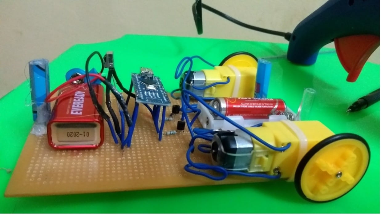
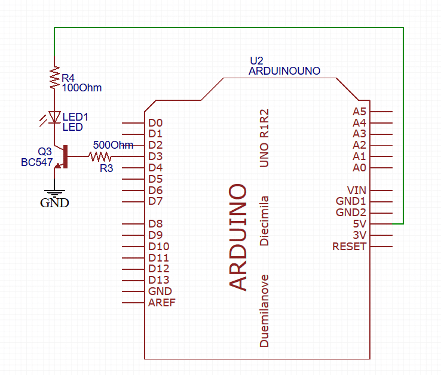
The car shown in fig Figure 1 has two 9V geared DC motor wheels which are powered by two 1.5V AA batteries in series. The power to the motor is given through BC547 transistors. BC 547 is a NPN general purpose transistor. It is commonly used in audio amplifiers and signal processing circuits. In this application, the transistor is used as a low side switch. The motor positive lead is always connected to the +3V supply. The negative terminal of the motor is connected to the ground through the transistor. Only when the transistor is conducting, the current flows through the motor. The transistor has collector, base and emitter terminals. The collector is connected to the negative terminal of the motor and emitter is connected to the ground. The base is connected to the signal from the Arduino through a 500 ohm resistor as shown in fig Figure 2 . The transistors of the left and right motor are connected to D3 and D5 digital output pins. The resistor is for limiting the flow of current into the base of the transistor. When both D3 and D5 pins are driven HIGH, both the transistors start conducting and the RC car moves forward. When only one of the transistors is driven HIGH, the car turns. It is not possible to reverse the car with this setup.
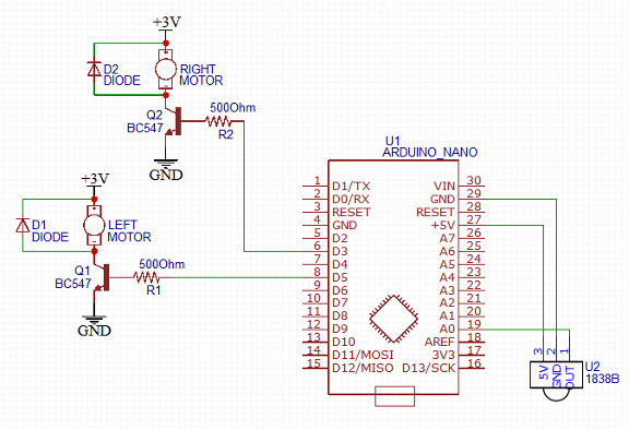
The VS1838B IR receiver is used to receive commands from a TV remote control (Tata Sky) or the transmitter connected to the laptop. It is compatible with common IR remote control data formats. The input voltage is 3V to 5V. It has 3 pins: Vcc, Output and Ground. The 5V power for the IR receiver is given from the Arduino itself, ensuring a common ground. Output pin is connected to D10 pin of Arduino. The widely used “IRremote.h” Arduino library is used to decode the received IR signals and convert them to integers that can then be acted upon.
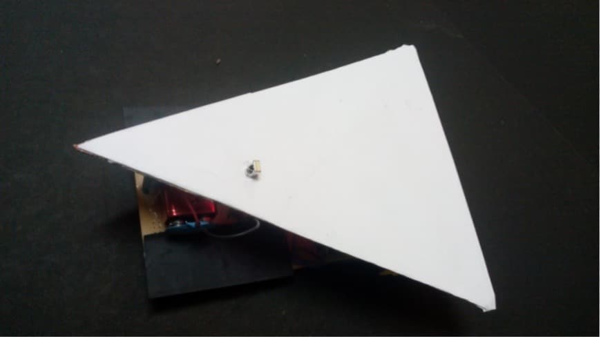
The completed car is covered with a white triangle made of cardboard (shown in Figure 7) so that a triangle shape is visible to the overhead camera to identify the car location and orientation. The VS1838B receiver pokes through the triangle so that it can receive the signals from the transmitter board or TV remote control.
IR receiver and transmitter setup
The codes received in the serial monitor of the Arduino Nano of the car when different buttons are pressed on the Tata Sky remote are given in Table 1. These codes where identified by connecting the receiving Arduino Nano to the computer using USB cable and logging its Serial monitor when different keys are pressed on the Tata Sky remote control (shown in figure).
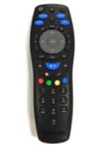
While in operation on the car, the Arduino Nano on the car listens for these codes continuously in a loop. In the Arduino code programmed on the car, the left, right and front key codes of Tata Sky remote have been assigned functions that make the car turn left right or go straight forward respectively. The code corresponding to number button keys 1,2,3,4 have been assigned to set the differential drive times to different durations. For example, pressing 1 and then left key makes the right motor spin for 500 milliseconds while the left motor is stopped. Pressing 2 and then left key makes the right motor spin for 1000 milliseconds while the left motor is stopped. Thus the extent of turning can be controlled. Similarly pressing red color key and forward button on remote makes the car go forward for 2 seconds, while pressing blue and forward makes the car go forward for 500 milliseconds.
Table 1 Codes for different buttons on Tata Sky remote
| Button in Tata Sky Remote | Integer value received |
| 0 to 10 numbers | 12582912 to 2582921 |
| Right | 12583003 |
| Left | 12583002 |
| Front | 12583000 |
| Back | 12583001 |
| Blue | 12583024 |
| Yellow | 12583023 |
| Green | 12583022 |
| Red | 12583021 |
| Play/Pause | 12582948 |
The IR transmitter board shown in Figure 5 is a simple perforated board containing a Arduino Uno driving an IR LED through a BC547 transistor as shown in Figure 6. The D3 digital PWM output pin is connected to the base of the transistor using the 500 ohm current limiting resistor. The collector of the transistor is connected to the led and the emitter is connected to common ground. The IR led is connected to the 5V pin of Arduino through the current limiting resistor.
The IRsend() command of “IRremote.h” library is used to send the codes corresponding to the different number keys of the Tata Sky remote. Thus the IR transmitter simply emulates the Tata Sky remote. The Arduino program on the Uno connected to IR transmitter monitors its Serial port in a loop. When the Python program doing the image processing routine outputs go forward/turn command to the serial port, the Arduino reads the character from the serial port, and transmits the corresponding IR signal through the IR LED. All the image processing and decision making about navigating the car is done by the Python program and it simply passes the commands to the Arduino Uno which then transmits it to the Arduino Nano on the Car.
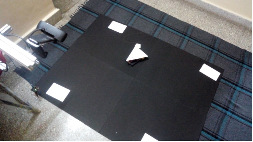
Image processing for target identification
A Logitech web camera mounted on a frame is used to continuously acquire images in a loop. The laptop acquires images from the webcam using the VideoCapture function of openCV. Each images is processed and a move command is given before the next image is taken. The flow chart of the overall python program is shown in Figure 8.
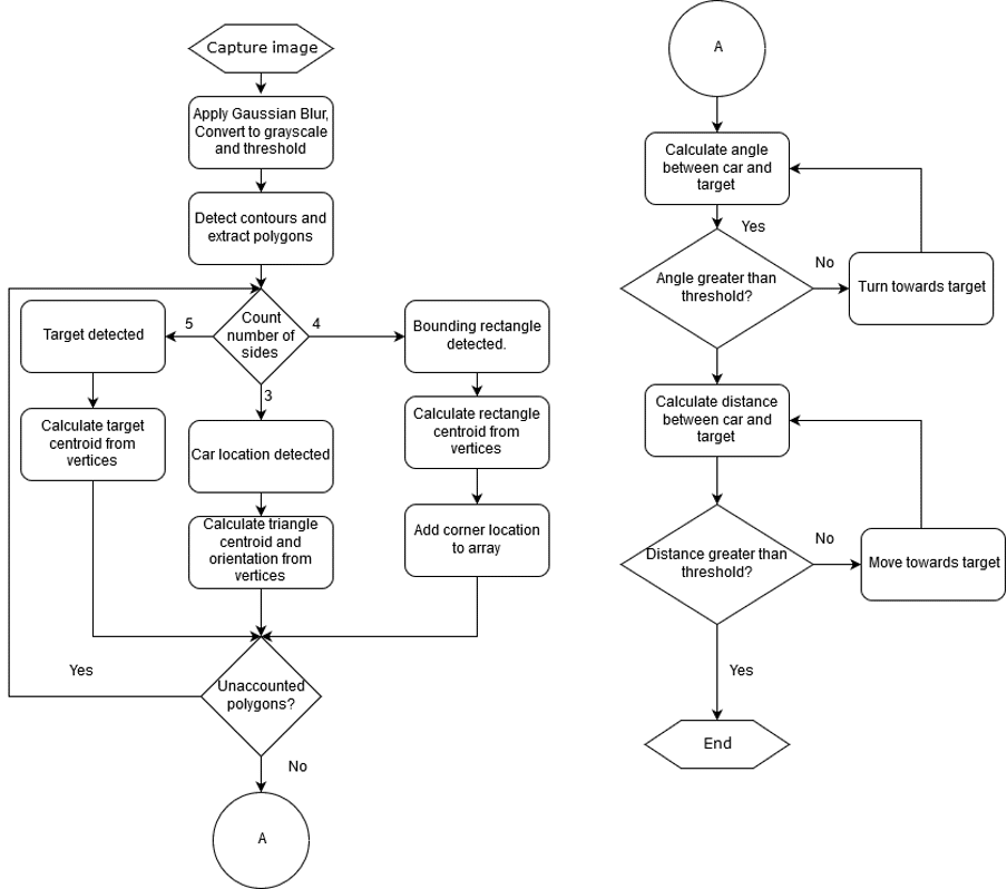
As the first step after acquiring the image, a Gaussian blur is applied to remove noise in the images. The colour image is converted into gray scale and a threshold of 210 is applied to differentiate white and black regions. All pixel values above 210 is treated as white and pixel values below 210 are treated as black. Thus gray scale is converted to black and white image, which is then given to contour finding function findContours() of openCV. The array of contours returned from findContours() is passed to approxPolyDP() function to extract polygons. Each of the returned polygon is tested for the number of sides. In the absence of spurious reflections, a pentagon, a triangle and 4 rectangles are detected in the black and white image. These detected contours are shown in Figure 9.
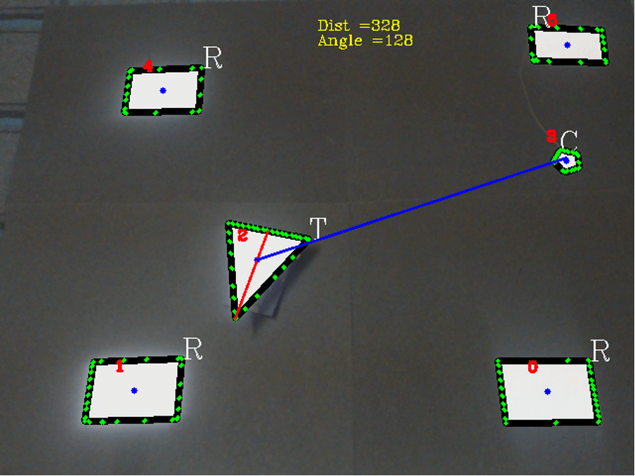
A line is drawn through the centroid of the triangle and the midpoint of the shortest side of the triangle. This line is treated as axis of the car. The line joining the centroid of the car triangle and target pentagon is treated as the path line. The angle between the path line and axis of the car is calculated for each image and a turn command is issued if the angle is more than 5 degrees. Move forward command is issued if the distance between the two centroids is more than the threshold. The distance check and angle check is done for each image and process is repeated until both the distance and angle are less than the threshold, at which point the car is considered to have reached the target. The four bounding rectangles are used to check whether the car is within the bounds of the matt black area.
Download Source Code
Conclusion
The entire setup was tested multiple times by moving the target marker to different locations within the bounding rectangles and checking if the car reached the target. The care reached the target within the threshold limit set most of the times. In spite of using matt black background with controlled constant lighting, there were spurious reflections which the code is not robust enough to account for. Since the python code is running on the laptop, the code could be expanded and made more robust to account for spurious reflections while finding the locations of the target and current location of the car. Regular polygon shaped obstacles can also be placed in the car path and the python module can be improved to plan a path that avoids these obstacles. The hardware of the car can be improved to have capability to go backwards by using a proper DC motor driver. The source files of the Arduino code for the transmitter and receiver along with the modular python code for image processing and navigation is provided along with this article so that they can be improved upon. Video showing the operation of the car, when manually controlled is posted in the following video.
Video on the operation of car when controlled by the python program is posted below: