


Generally, the total number of appliances that can be controlled without using a microcontroller (MCU) is limited to three or four. One possible solution to this limitation is described in this project. Using this circuit, you can control Multiple electrical appliances (up to 16) using HT12E and HT12D in the transmitter and receiver sections, respectively.
The ICs convert BCD parallel data into serial data. Since HT12E can take BCD inputs, you can feed (24=16 different types) many inputs that can be decoded at the receiver section easily.
Multiple Appliances Control Circuit
The circuit is divided into three main sections:
- Transmitter
- Receiver
- Bistable
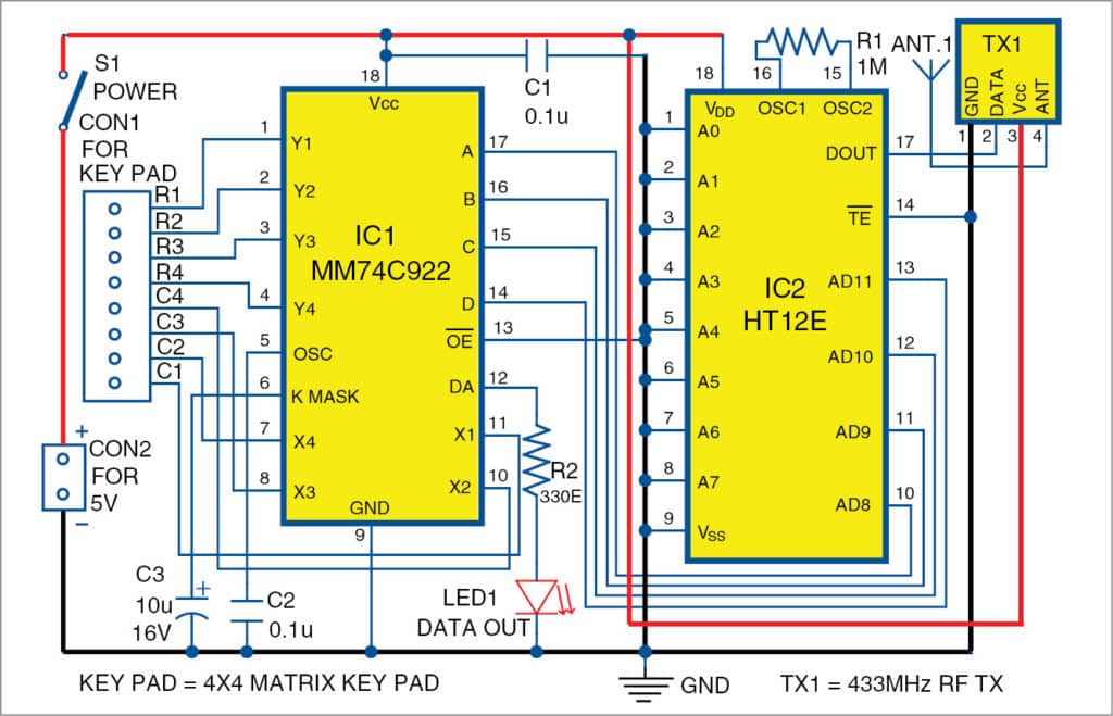
Transmitter Section
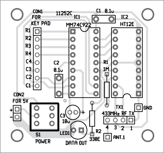
The circuit diagram of the transmitter section is shown in Fig. 1. It is built around a 4×4 matrix keypad connected across connector CON1, key encoder MM74C922 (IC1), encoder HT12E (IC2), 433MHz RF transmitter module (TX1) and a few other components.
Here, MM74C922 is used to get BCD output on pressing any button on the keypad.
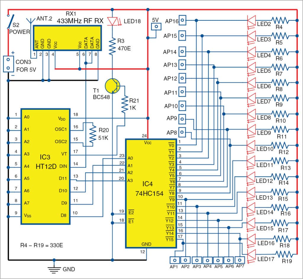
Receiver Section
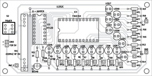
The circuit diagram of the receiver section is shown in Fig. 2. It is built around a 433MHz RF receiver module (RX1), decoder HT12D (IC3), 4- to 16-line decoder 74HC154 (IC4), and a few other components. Here, 74HC154 is used to decode each BCD code into the corresponding output (AP1 through AP16).
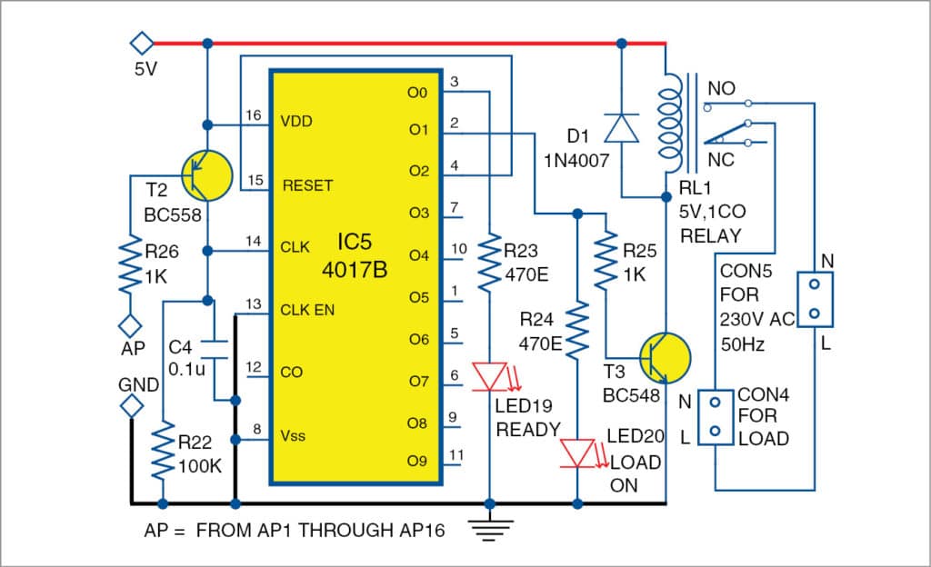
The Signal received at the receiver side is active low till a pushbutton (input from the keyboard) is pressed at the transmitter section. In order to control an appliance with this signal, make a bistable circuit that will convert the single-pulse signal into two stable states (high and low) to drive a relay.
Bistable Section
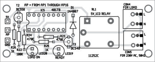
The circuit diagram of the bistable section is shown in Fig. 3. It is built around decade counter 4017B (IC5), 5V relay (RL1), and a few other components. Here, 4017B is used as a bistable multivibrator. The output state of the bistable does not change until the next input is received. AP is the appliance control input to IC5. It could be any one of the inputs from AP1 through AP16, from IC4. Connect the appliance to be controlled across the contacts of the relay.
Working
The working of the circuit is simple. When you press a key on the keypad, the input signal is encoded and transmitted through the RF transmitter module.
The receiver receives the serial data and converts it into parallel data (BCD). This BCD data is available across the output pins of IC4.
At each output pin of IC4, a bistable circuit is connected, which converts the signal into two stable states depending on the status of the keypad.
For example, if input key 1 (not shown here) is pressed, AP1 will be low and RL1 will be energized. The load or appliance connected at CON4 will be on at the same time LED17 and LED20 will be on.
And, when input key 0 or any other key is pressed again, AP1 will go high, RL1 will be de-energized and load will be turned off and LED17 and LED20 will also be off.
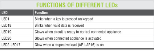
LEDs connected in these circuits have a particular purpose, as shown in the table.
PCB and Layout Design
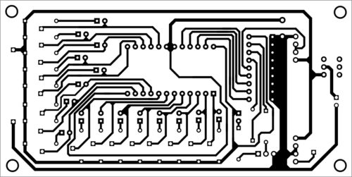
An actual-size PCB layout of the transmitter circuit is shown in Fig. 4 and the layout of its components is in Fig. 5. Assemble the circuit on the designed PCB. Also, connect TX1 to the PCB.

An actual-size PCB layout of the receiver circuit is shown in Fig. 6 and the layout of its components is in Fig. 7. Assemble the circuit on the designed PCB. Also, connect RX1 to the PCB.
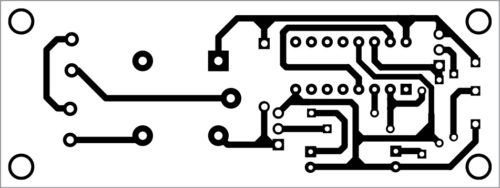
An actual-size PCB layout of the bistable circuit is shown in Fig. 8 and the layout of its components is in Fig. 9. Assemble the circuit on the designed PCB. You can assemble 16 bistable units with the same circuit depending on your requirement for the number of appliances you would like to control.
Download PCB and Component Layout PDFs: click here
After assembling all three units, connect the receiver unit with the bistable unit using an external connector. Connect these to each output of IC4. Also, connect the keypad across CON1 on the transmitter side – one antenna each on TX1 and RX1. Connect 230V AC, 50Hz across CON5, and load/appliance across CON4. Now, the circuit is ready to use.
Sanjay Kumar Gupta is an electronics hobbyist