


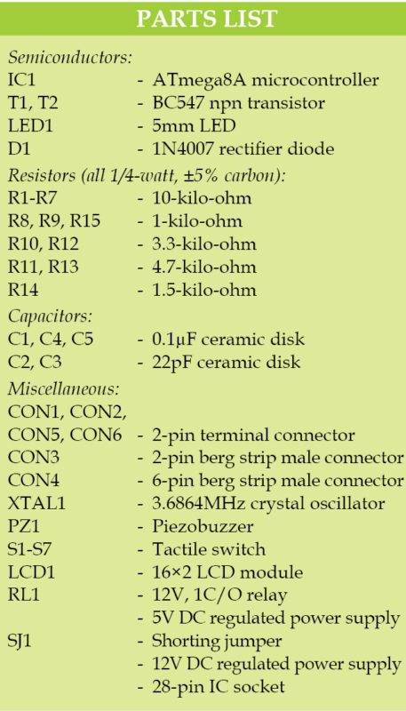
 Sometimes there is a need to switch on or off electrical appliances or gadgets after a predetermined time. The circuit presented here can switch on/off any electrical appliance (load) through a relay switch after the specified time set in minutes or seconds.
The timer can be easily set with four switches (S3 through S6) to select minutes/seconds, hundredths, tenths and units. Two more switches are used to start (S2) and stop (S1) the timer.
Circuit and Working
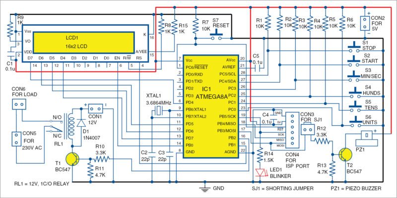
Circuit diagram of the countdown timer is shown in Fig. 1. ATmega8A (IC1) from Atmel is at the heart of the circuit. Associated components include a 16×2 liquid crystal display (LCD1), two BC547 transistors (T1 and T2), a piezobuzzer (PZ1), a 12V single-changeover (1C/O) relay and a few other components.
The system works in three modes: started, stopped and setting.
Started means the countdown is under process and settings are not allowed.
Stopped means the countdown has stopped and the user can change settings to start the countdown timer afresh.
In setting mode, the input switches (S3 through S6) are enabled for countdown timer settings.
When start switch (S2) is pressed, relay RL1 energises, and the countdown starts. The timer stops automatically when the countdown reaches 000 or stop button (S1) is pressed. The status of countdown is shown on LCD1.
A beep is generated by the piezobuzzer when the countdown reaches below ten seconds and stops when the countdown reaches 000. Jumper J1 can be disconnected if the buzzer is not required. The power supply to relay RL1 depends on the coil voltage of the relay (like 5V, 6V or 12V). Here, we used 12V DC at CON1 for the relay.
In stopped or setting mode, LED1 blinks every ten seconds. When start (S2) button is pressed, LED1 blinks every second.
Software
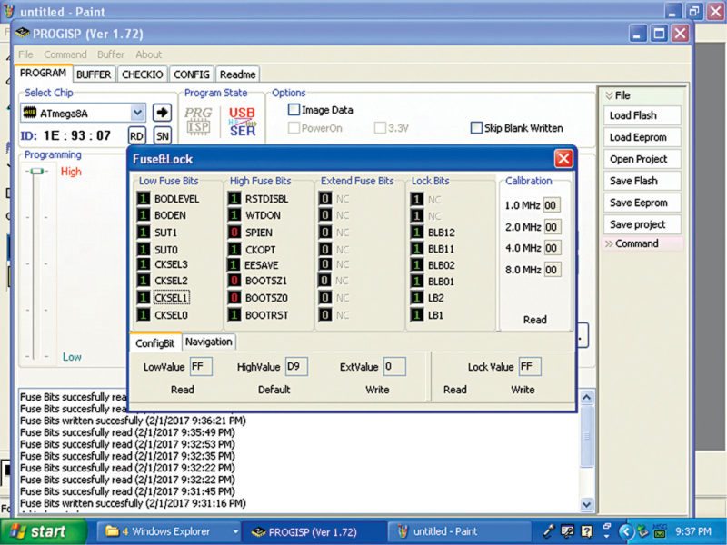
The software is written in ‘C’ language and compiled using an AVR Studio 4 software. You can use any suitable software to burn the hex code into the microcontroller through ISP port. At EFY Lab, we used ProgISP programmer for the purpose.
Before programming, set fuse bits for the 3.6864MHz crystal option as shown in Fig. 2.
Construction and testing
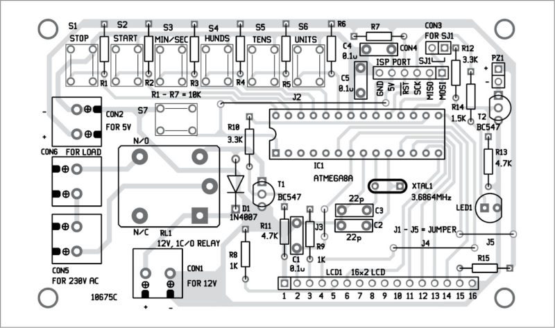
An actual-size, PCB layout for the countdown timer is shown in Fig. 3 and its components layout in Fig. 4. After assembling the circuit, enclose it in a suitable box.
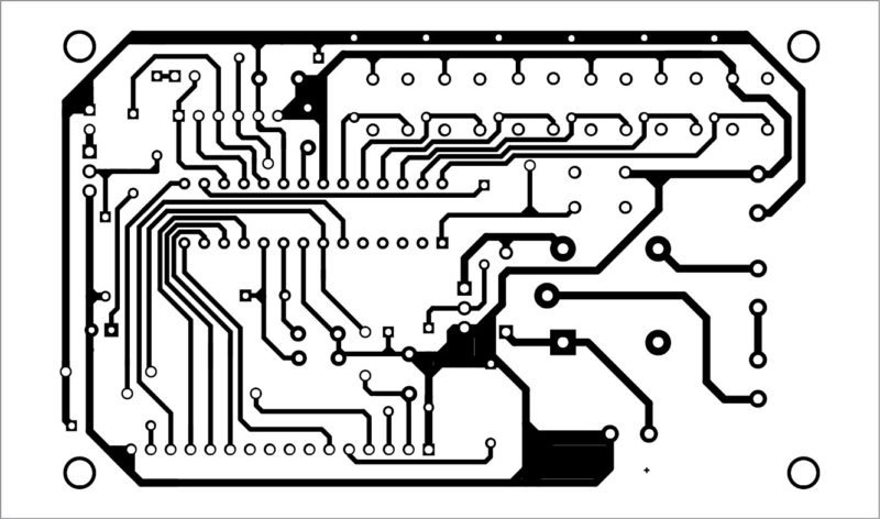
Insert the programmed MCU in the IC socket on the PCB. Connect an electrical load (say, 100W bulb) across CON6, and 230V AC mains across CON5.
Now, power on the circuit by connecting a 5V DC supply at CON2. LED1 will glow and the buzzer will sound for about one second, followed by display of ‘countdown timer’ message on LCD. The system is now ready to use, waiting for the user input.

Thanks for your project, I’m running Linux so will have to find a way of programming the controller with your software. I’m not a programmer more of a hardware person, left all this behind when HC11 started to make headway. One thing do you have a part number for the “tactile switches” used? As I’ll have to find a suitable part in Australia, I’ll probably change the relay to a DPDT so that I can control the safelght and wire the output for local safty conditions.