


 This data logging system can be used to interface an external or internal sensor of Raspberry Pi Pico board. The project has many advantages, including the use of internal temperature sensor of Raspberry Pi Pico board; so an external temperature sensor is not required. Second, the easily detachable microSD card can be used to record different temperature data at a particular place or industrial setup. The SD card can be removed and carried to laboratory or control room for analysis or future reference. The project also includes optional external sensors, such as force and light sensors.
Components required for the project are given in the Table below.

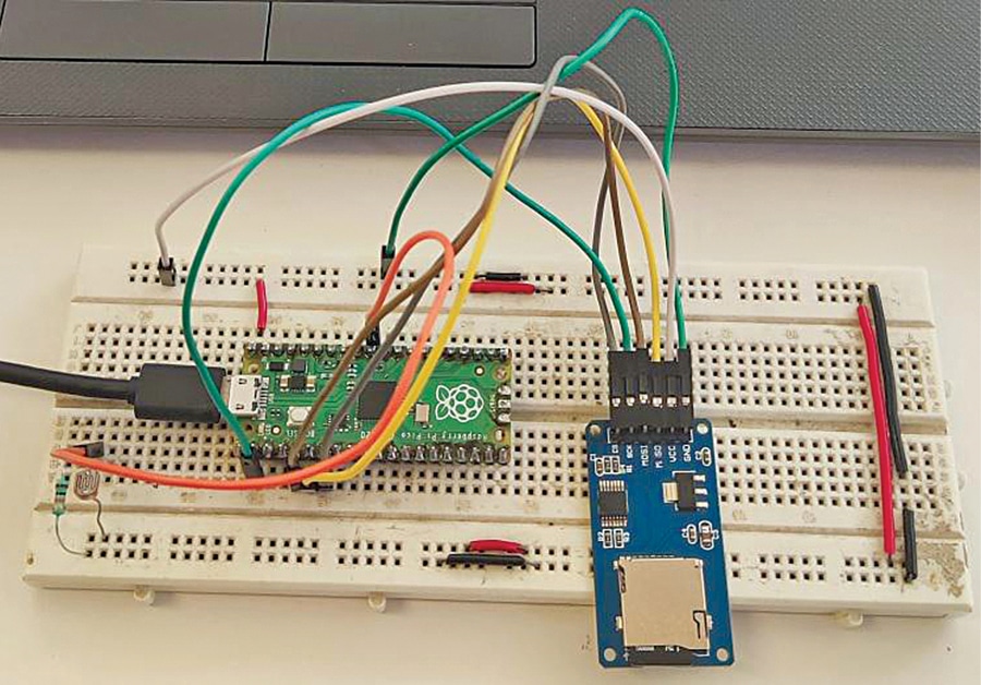
The author’s prototype wired on the breadboard is shown in Fig. 1 and the connection of data logging system with microSD card and Raspberry Pi Pico is shown in Fig. 2. An LDR or any other suitable analogue sensor, such as the force sensor shown, may be used.
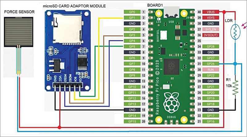
The setup uses serial peripheral interface (SPI) pins MOSI, MISO, CS, and CLK of Raspberry Pi Pico Board1. External sensor (light sensor, light dependent resistor, or force sensor) is connected to GP26 pin of Board1.
LDR sensor is used to record light condition in the area where it is installed. The microSD card module is interfaced with Raspberry Pi Pico board pins GP1, GP3, GP4, and GP5. VBUS from the board is used as power supply for microSD card and LDR. A 10k pull-down resistor is connected to GP26 pin of Board1 for interfacing external sensors.
Software
The project is controlled by the Python program developed on Mu editor. Mu editor is a simple code editor that works with Adafruit CircuitPython boards, including Raspberry Pi Pico, and on most operating systems, including Windows and Linux. CircuitPython is based on Python programming language and is easy to understand.
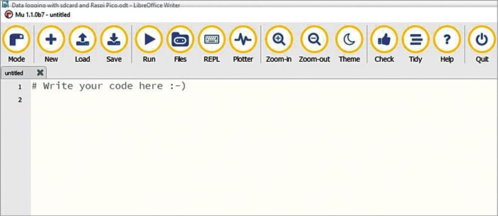
Both Mu and CircuitPython are required for this project. Mu editor can be downloaded from https://codewith.mu and then installed using instructions given at the link. After installing Mu editor, run it and you will see the window shown in Fig. 3.
CircuitPython version 7.1.1 was used during testing of this project. CircuitPython board requires a bootloader called UF2 (USB flashing format) that makes installing and updating CircuitPython a quick and easy process. Download the most recent version of CircuitPython bootloader .UF2 file from click this link.
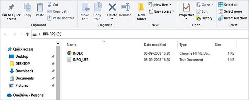
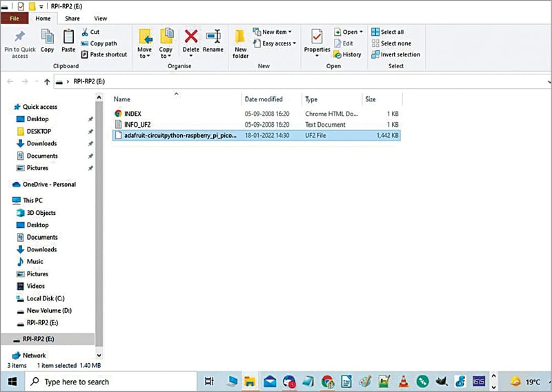
Installing CircuitPython on the board is easy. Just copy and paste the file as explained here. First press the BOOTSEL button on the Raspberry Pi Pico board, while inserting the USB cable of the RPI board to laptop/PC, and release it after a new drive (RPI-RP2) window appears, as shown in Fig. 4.
Next, copy adafruit-circuitpython-raspberry_pi_pico-en_US-7.1.1.uf2 file downloaded in previous step. Paste it into the new window, as shown in Fig. 5. Now open Mu editor window and close all other windows.
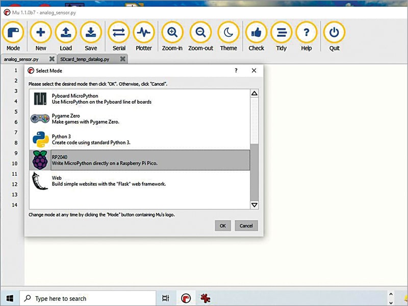
Next, the first thing to do in Mu is to select ‘Mode’ from the main menu. In this project, you should select RP2040 option in Select Mode window, as shown in Fig. 6.
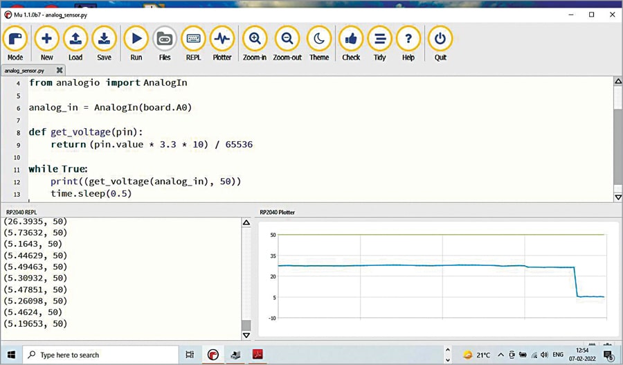
Start coding on the Mu editor window or load the existing code. You can load the analog_sensor.py code that comes along with this project. This code will work with either LDR or force sensor but not with both at the same time.
Connect LDR to the circuit, as shown in the schematic, and run the code by clicking Run button. When you cover the LDR with an opaque object and uncover it again, you will see the light intensity’s arbitrary values vary between 0 and 32, with 0 being the darkest and 32 being the brightest light.
An additional feature of Mu is its ability to display the data waveform. When you select the Plotter option from the main menu, you will see the output waveform, as shown in Fig. 7. Similarly, you can replace LDR with any other analogue sensor like force sensor. The sensor data will be displayed on the screen along with the waveform.
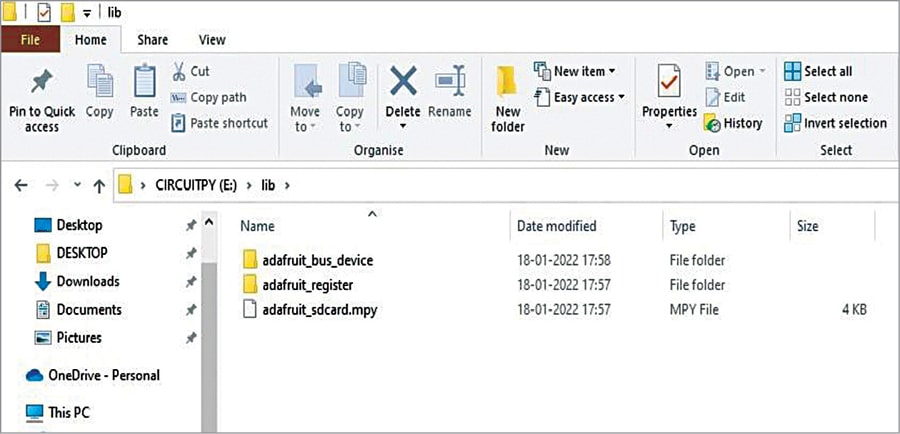
Let us now explore the inbuilt temperature sensor on Raspberry Pi Pico board and store the temperature data on the microSD card that is normally used in your mobile phone. Here, we use CircuitPython libraries along with the main code (Sdcard_temp_data.py). You need to import adafruit libraries for SD card to interface it with the Raspberry Pi Pico board. For that download the libraries (Bundle for Version 7.x) from this link.
Unzip the Bundle folder and copy adafruit_bus_device and adafruit_register folders, paste them into ‘lib’ folder in CIRCUITPY(E) drive. Also copy adafruit_sdcard.mpy file from the Bundle folder and paste into ‘lib’ folder, as shown in Fig. 8.
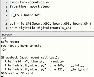
Open Mu editor and load the main code under Code.py file. Save the file and run it. If something goes wrong, you will get error message at the bottom of the Mu editor window. For example, if SD card is not connected properly to the circuit, you will get “OSError: no SD card” error message, as shown in Fig. 9.
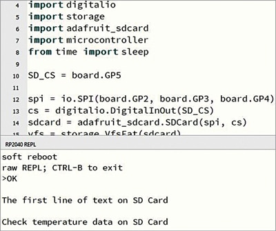
If everything is fine, instead of error message you will see following text (see Fig. 10) below the Mu editor window: “The first line of text on SD card, Check temperature data on SD card”
Now, quit Mu editor and unplug the SD card from its adaptor. Insert SD card into the microSD card slot in your laptop/PC and check the various temperature values available in text file format.
Construction and testing
The whole circuit can be assembled on a breadboard or general-purpose PCB. Most Raspberry Pi Pico boards do not come with header pins connected or soldered on the boards. Without these pins, the board cannot be interfaced with external devices, such as sensors, motors, or any device required for the project. Wires can be soldered directly onto the holes provided on the board, but that is a bit risky as you may damage the board.
So, to access GPIO pins, solder each pin carefully using male Berg strip connectors with an appropriate soldering iron. You can then either mount the pins on the breadboard or connect each pin with jumper wire to other components or modules.
After all connections are done, recheck correct polarities, specially Vcc and ground pins. Note that VBUS at pin 40 is typically 5V, which is the main Vcc supply in the circuit. Before inserting the microSD card first format it in FAT32 system and only then insert it into the slot provided in the adaptor.
When you plug in your Raspberry Pi Pico to your laptop the first time, Mu editor attempts to auto-detect your board on start-up and searches for CIRCUITPY drive in the board. So, prior to this, ensure that CircuitPython is properly installed in the drive, as explained above. Next, select the mode and run the code analog_sensor.py.
If you get proper sensor output data and waveform, open the main code by clicking on Load option on the main menu bar. Run the code and make sure you get the output message at the bottom of the Mu editor window. You can quit the program and switch off the circuit any time you wish to check the sensor data on the SD card from any computer having microSD card slot.
Download source code
Sani Theo is an electronics enthusiast, circuit designer, and technical editor
