


Energy harvesting devices such as piezoelectric elements and antennas capture ambient energy, but this energy has to be converted to DC for load and energy storage devices. For this high-efficiency power harvesting circuits are required. This article discusses important design aspects of energy harvesting circuits and their implementation.
Recent developments in ultra-low-power circuit designs have reduced the power consumption of portable electronic devices and low-power wireless sensors significantly. The power now required has been reduced to just picowatts in the standby mode and nanowatts in the active mode, with the devices operating on an ultra-low duty cycle. These breakthroughs harvest energy from ambient vibrations, radio frequency, static electricity, and other ambient sources, making the best use of energy harvesting solutions.
The energy harvesters make it possible to achieve battery-less operation in low-power devices. The previous article on battery-less solutions discussed some popular energy harvesting techniques that produce enough power to run specific low-power devices. But after capturing the power from source, it needs to be rectified and conditioned before it is fit for use.
A typical ambient energy harvesting circuit has a transducer that translates the ambient energy into electrical energy. In the case of vibrational energy harvesters, these transducers are piezoelectric elements, mechanical oscillators, electromagnetic vibrational harvesters, etc. In the case of RF energy harvesting, the transducer is the antenna. Likewise, there are various other transducers for different energy sources.
The energy converted by the transducers is rectified to generate a DC voltage suitable for load and supercapacitors (for energy storage). The main aim while designing energy harvesting circuits is to maintain high efficiency at every stage. To ensure that, we need an impedance matching circuit between the transducer and the rectifier for maximum power transfer.
After rectification, the voltage may be multiplied by voltage multiplier circuits for compatibility. Now, most of the battery-less low-power devices employ supercapacitors for energy storage. To facilitate such storage, a switch-mode DC-DC converter circuit can be used. Some sophisticated systems use adaptive energy storage systems that compensate for the shortcomings of single energy storage devices.
For ensuring smooth output and high efficiency, feedback circuits can be used to manage the converter circuits. The goal is not only to optimise the power harvested but also to maximise the energy conversion efficiency.
With this, we start discussing the very first stage that ensures maximum power transfer from the transducer to the rectifier circuit—an impedance-matching circuit.
Impedance matching
Impedance matching circuit is crucial in optimising the performance of the energy harvesting system. Mismatch in the impedance of transducers and rectifiers degrades the power conversion efficiency of the energy harvester circuit.
Let us consider an example of RF energy harvesting system, where, to increase the conversion efficiency, the designed circuit should resonate at the targeted frequency. A matching circuit has to be designed to match the impedance of the multiplier circuit to the standard 50-ohm antenna for allowing maximum power transfer from the antenna to the circuit.
To match the impedance, it is necessary to first identify the input impedance of the rectifier circuit, which generally consists of nonlinear devices such as diodes and transistors. Small-signal modeling techniques for approximating the behaviour of these nonlinear devices cannot be used due to the large input signal and absence of an input DC bias. The large input signals without any DC bias results in the rectifying device to operate in different regions of operation within the same input cycle. This leads to variation in the input impedance of the rectifier circuit.
For such systems, designing impedance matching circuits is complicated. You need to identify input impedance under all the operating regions such as the subthreshold region, ohmic region, and saturated region according to different DC-bias points, and then design multiple matching circuits accordingly.
However, small variation in input signal guarantees that small-signal parameters of the transistors remain relatively constant, and the calculated input impedance accurately predicts the behavior of the circuit during the normal operation. A fixed impedance matching circuit can then be designed.
There are two popular methods by which impedance matching can be executed, one by fixed LC (inductor-capacitor) impedance matching circuits, and the other by using a transformer to achieve impedance matching. Transformer based matching has an advantage of lower die area and robustness compared to the LC matching method.
Let us first have a look at the LC based matching method. We start with simple topology consisting of an inductor and a capacitor. The difference between the impedances of the rectifier and the transducer dictates the quality factor and the values of capacitor and inductor.
There are four different possible versions of LC circuit, two of them would be low-pass and the other two would be high-pass versions. The low-pass versions are generally employed in RF (radio frequency) circuits since they attenuate harmonics, noise, and other undesired signals. But in our case, we need energy sources from the maximum bandwidth possible. Therefore, the topology shown in Fig. 1 works best in our case.
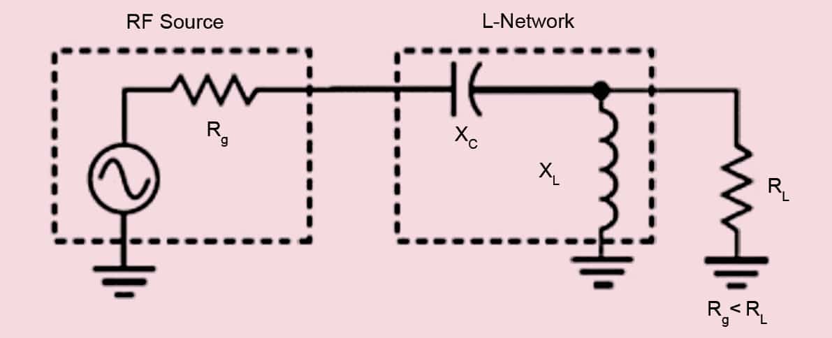
The circuit in Fig. 1 works when the input impedance of the rectifier is greater than the output impedance of the transducer. For identifying the values of inductor and capacitor, you need both the aforementioned impedances and a desired frequency. Then you need to plugin the numbers in the following set of equations:

