


 This article is about designing an Android app for communication with HC-05 Bluetooth module using MIT App Inventor (open source), a block-based programming tool. MIT App Inventor is used to create apps without any text-based programming language or bulky software in your PC. Arduino Uno board along with a Bluetooth module and an LED is used for testing the app.
MIT App Inventor
Open MIT App Inventor in Google Chrome or Mozilla Firefox—not supported in Internet Explorer. A window will open, as shown in Fig. 1.

Click on Create apps! And you will reach the login page of Google account. Sign in with your Google credentials. After signing in, a new window will open (Fig. 2).

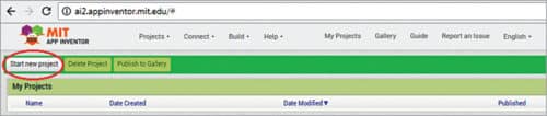
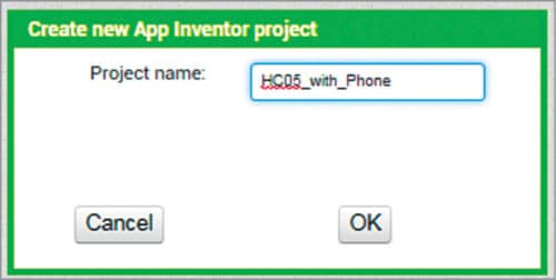
Click on Start new project. A dialogue box will pop up for you to enter the name of your project. For example, here we used HC05_with_Phone (Fig. 3).
The project window will open (Fig. 4). Here, you will see two headings on the top-right, namely, Designer and Blocks. Under Designer head you find windows such as Palette, Viewer, Components and Properties, which are used to design an app. The user interface is designed using Designer, where you can select the various components for the app.
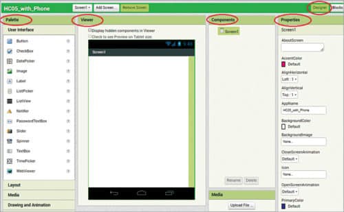
Blocks editor provides the functionality for the components. Main programming is done in Blocks section because MIT App Inventor is a block-based programming.
App Inventor Designer section
Details of each window in Designer are given below.
Palette
Here, you can pick the different components you want to use for your project.
Viewer. Here, you can see what your app will look like.
Components
This is where you can see all the components you have used in your project.
Properties
Here, you can change the properties of each component you used, including size, colour, default text and so on.
Now, let us learn about the horizontal and vertical arrangement layouts in Android apps.
Vertical arrangement layout
When you use vertical arrangement, all components for the user interface—such as buttons, labels and edit text—will be arranged vertically, or laid out from top to bottom.
Horizontal arrangement layout
When you use horizontal arrangement, all components will be arranged horizontally, or left-to-right fashion.
There is one vertical and five horizontal arrangements in this project.
Vertical arrangement
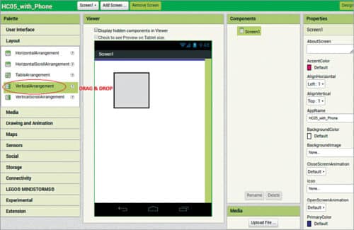
Select VerticalArrangement component from the left side and drag it to Viewer window (Fig. 5). To do that, go to Palette window, where you will see User Interface. Scroll down and select Layout→VerticalArrangement. Click and hold it, and then drag it over the cellphone-shaped Screen1 box.
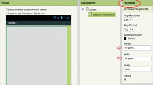
Go to Properties of VerticalArrangment1 at the top-right, and select the height and width, as shown in Fig. 6.
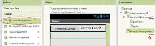
First horizontal arrangement
Select Palette→Layout→HorizontalArrangement. Drag it over the vertical layout. Go to Properties and select both Align Horizontal and Vertical as Center, Height as 50 pixels and Width as Fill Parent.
ListPicker
This button is used to display the list of devices/items available in Bluetooth devices. It also handles the selection.
Select Palette→User Interface→ListPicker. Drag it over HorizontalArrangement layout. Go to Properties of ListPicker and change the following parameters:
- Background colour: light grey
- Font bold (check)
- Font size: 14.0
- Height: 60 pixels
- Width: 50 per cent
- Text: Available Bluetooth Devices
- Text alignment: centre
Note: You can rename ListPicker1 or other components from Components window using Rename option.
Label
This option is used to show the connected Bluetooth Device. Select Palette→User Interface→Label. Drag it over HorizontalArrangement1 layout. Go to Properties of HorizontalArrangement1 and change the following:
- Background colour: light grey
- Height: 50 pixels
- Width: 50 per cent
- Text: Connected Device Will Show Here
- Text alignment: centre
Second horizontal arrangement
Go to Palette→Layout→HorizontalArrangement and drag it over VerticalArrangement. Go to Properties of HorizontalArrangement2 and change the following.
- Align: horizontal – centre
- Height: 50 pixels
- Width: fill parent
Select Palette→User Interface→Label and drag it over HorizontalArrangement2. Label it to show the status of the Bluetooth connection, as connected or not. Go to Properties of Label2 and make the following changes:
- Background colour: orange
- Font size: 19
- Height: 40 pixels
- Width: fill parent
- Text: Not Connected
- Text alignment: centre

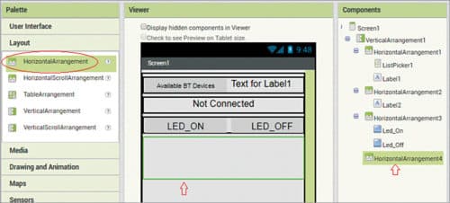
Third horizontal arrangement
Go to Palette→Layout→Horizontal Arrangement layout and drag it over the vertical layout. Go to Properties and select Align Horizontal as Center, Height as 50 pixels and Width as Fill Parent.
Select Palette→User Interface→Button and drag it over HorizontalArrangement3. Go to Properties of Button and change the following:
- Background colour: green
- Font size: 19.0
- Height: 50 pixels
- Width: 50 per cent
- Text: LED_ON
- Text alignment: centre

Third horizontal arrangement
Go to Components, select button_1 and click on Rename. Change its name to LED_ON. Select Palette→User Interface→Button and drag it over HorizontalArrangement3. Go to Properties of Button and make the following changes:
- Background colour: red
- Font size: 19.0
- Height: 50 pixels
- Width: 50 per cent
- Text: LED_OFF
- Text alignment: centre
Go to Components, select button_2 and click on Rename. Change its name to LED_OFF.
Fourth horizontal arrangement
Select Palette→Layout→Horizontal Arrangement and drag it over the vertical layout. Go to Properties of HorizontalArrangement4 and make the following changes:
- Height: 80 pixels
- Width: fill parent
Text Box
This is used to receive data from the connected device. Reception of data is implemented using a timer. The client checks to see if data is available. If yes, it reads and displays the data on the fourth horizontal arrangement. For this, add Clock Sensor component later, which is a hidden component.
Select Palette→User Interface→TextBox and drag it over HorizontalArrangement4. Go to Properties of HorizontalArrangement4 and make the following changes:
- Height: fill parent
- Width: fill parent
- Hint: serial data will show here
Adding disconnect button
Select Palette→User Interface→Button and drag it over Vertical Arrangement1. Go to Properties of Button and make the following changes:
- Background colour: pink
- Font size: 19
- Height: automatic
- Width: fill parent
- Text: disconnect
- Text alignment: centre

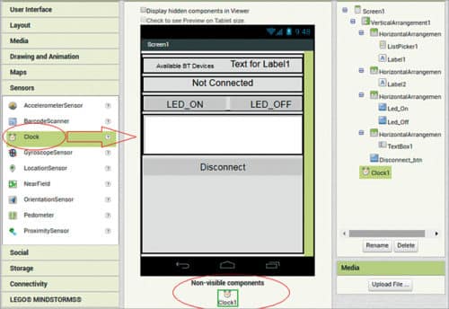
Non-visible component
Now, add some non-visible components. Palette→Sensor→Clock and drag it to Screen1.
Adding Bluetooth Client
Bluetooth Client component is used to establish Bluetooth connection. Select Palette→Connectivity→Bluetooth Client and drag it to Screen1.
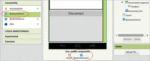
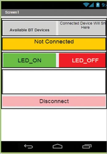
Finally, the app will look as shown in Fig. 14.
App Inventor Blocks section
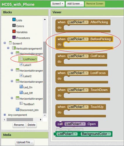
Now, let us define the working of each component as per our requirement. Blocks section (Fig. 15) is where you provide the functionality to your selected components. There are built-in blocks that can handle things like Maths, logic and text, which you can use with each component that you have added. In addition to these components, the project has its own set of blocks specific to its own events, methods and properties.

Click on Blocks at the top-right corner in Screen1. You will get a new window. Click on ListPicker1, as shown in Fig. 16. Select ListPicker1 BeforePicking event, and drag and drop it over Viewer window.
From ListPicker1, select Set ListPicker1.Elements To, and drag and drop it over Viewer window. Then, go to BluetoothClient1 under Screen1 and select BluetoothClient1. AddressAndNames, and drag and drop it over Viewer window. Arrange all events in a similar fashion, as shown in Fig. 17.

BeforePicking()
This is the event to raise when Button is clicked. The event occurs before the list of items is displayed. It is used to prepare the list before it is shown. It sets the elements of ListPicker to available Bluetooth devices by their name and address.
AfterPicking()
This event is to be raised after the picker activity returns its result and properties have been filled in. Select ListPicker1.AfterPicking and go to built-in block Logic. Select another if then event, as shown in Fig. 17.
If if condition is satisfied or true, function BluetoothClient1 will be connected to a device from ListPicker section. It will set label1 text as Connected BT Device and label2 text as Connected, and change the text colour to green.
Now, add blocks for LED_ON and LED_OFF buttons, as shown in Fig. 18.

Here, send 1 to turn on the LED and 0 to turn it off. You can also send characters or strings according to the code.
Next, add an event for LED_ON button. When this button is clicked, call BluetoothClient1.SendText function to send text as 1. Do the same for LED_OFF; send 0 on clicking.
Adding clock
Select an event from Clock1.Timer, as shown in Fig. 19.

Here, clock is used to receive data from the client.
From Blocks on the left side, select and logic and drag it over Viewer window. This returns true if both conditions are satisfied. Then, select BluetoothClient1.IsConnected and attach it to ‘and’ logic to one side. Now, go to Math, select ‘=’ logic and select greater than (>) symbol.
Select BytesAvailableToReceive function of BluetoothClient1, which is greater than 0. For attaching 0, select a text string and enter 0. Here, 0 means bytes are available.
If if condition is true, convert Bytes Available on Bluetooth into text and set TextBox1.Text as the available text.
Adding Disconnect
Select Disconnect from Blocks. When it is clicked, call a function of BluetoothClient1.Disconnect, and set label1 to Connected Device Will Show Here and label2 to Disconnected. And, change colour to red, as shown in Fig. 19. With this, the application designing process is completed.
(Note. You can also refer to ‘How To Make Android App’ doc file included along with the source code given below)
Generating Android application file
The next step is to check the above app on an Android smartphone. For this, make an .apk file of the app. Note that you have three options for setting up live testing of the app, as given below.
1. If you have a wireless Internet connection on your PC and Android device, you can start building the app using MIT App Inventor without downloading any software to your computer. This option is used in this article, as explained above. For working offline, you need App Inventor Companion app on your device and App Inventor 2 Setup on your PC.
2. If you do not have a wireless Internet connection, install the software on your computer so that you can connect to your Android device over USB.
3. If you do not have an Android device but PC is available, use Emulator on your PC.
On the top of MIT App Inventor, there is Build option. Click on it and you will have two options to get .apk file. Select any option, you will get the app in .apk form. Download .apk and install it on your smartphone.
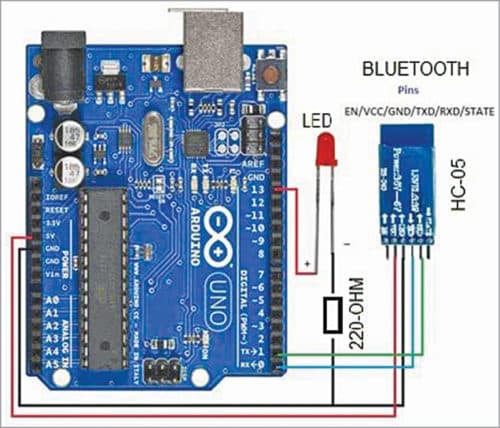
Testing Android app with Bluetooth module
To test the app, make the circuit with Bluetooth module (HC-05), as shown in Fig. 20. Upload the source code (HC05_Tested.ino) to Arduino Uno using a USB cable and Arduino IDE. The source code is given below.
int led=13;
void setup() {
pinMode(led,OUTPUT);
Serial.begin(9600);
}
void loop() {
if(Serial.available()>0){
int a = Serial.read();
if(a==’1’){
digitalWrite(led,HIGH);
Serial.println(“Led is On”);
}
else if(a==’0’){
digitalWrite(led,LOW);
Serial.println(“Led is Off”);
}
}
}
Connect HC-05 Bluetooth module with your Android’s Bluetooth (from setting). Next, open HC05_with_phone app, connect Bluetooth by clicking on Available Bluetooth device and select HC-05. You will see Connected message on your cellphone. You can now turn on or turn off the LED (LED1). Status of the LED will also be shown on the app.
Download source folder: click here
Mahendra Raisinghani and Sagar Raj Gupta are co-founders of Shoolin Labs, Jaipur
Hi sir, I am getting the following error on the phone
Error 507: Unable to connect. Is the device turned on?
Me too…Bluetooth module is not being connected to mobile.
Hi, can I receive a string with the app and process it, for example, convert from binary to decimal?
Hi,
when I build this, then I am getting label 1 as True or False.
I want to see the name of connected Bluetooth device. Please suggest