


 “The first Batteryless remote that can work for years”
There is much chemical waste being generated with billions of remotes being used. The waste produced from batteries keeps increasing annually. This DIY design is a super-efficient circuit that can harvest energy from the environment and power a remote. Since low power is needed for a remote battery the circuits can be eliminated saving tons of chemical waste each year.
For every button pressed on the remote, the kinetic energy used does not go waste is harvested using a circuit. The energy produced from this circuit is used to switch or carry out the function(as programmed) for the remote. The light in a room is used and the energy harvested is used for the remote, eliminating the need for a battery.
Video Tutorial:
The following components are needed for this project.
Bill Of Materials
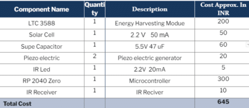
Design
The energy produced is harvested during the function of pressing a key on the remote. This mechanical energy is converted to electric energy. A small solar cell is also used to harvest photonic energy from the light in a room. All of the energy harvested is stored in a super capacitor. The remote runs on the stored energy. Thus whenever a switch is pressed, the electric energy is used to light the IR LED and a signal is given to the receiver to perform the functions given.
The Piezoelectric generator is first connected to input pins PZ1 and PZ2 of LTC 3588. Next, the solar cell is connected to the Vin pin and GND pin. At the output, an IR LED is connected with a switch and a supercapacitor as shown in the circuit diagram (Refer Fig 3).
When the piezo metal is pressed, the generated energy makes the IR LED glow, thus sending a signal to the receiver circuit. The solar cell is also connected to the supercapacitor that keeps getting charged such that the remote can be used even in the dark, with a slight press on the piezo element.
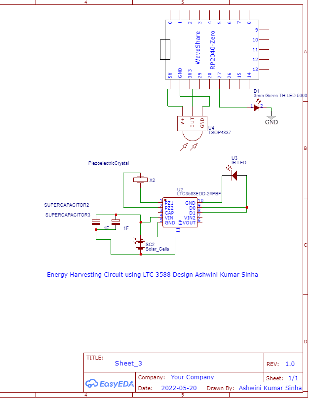
The IR receiver can be connected with pin 29 and programmed to control the LED. Any other function can also be programmed for the IR signal received from the IR remote. The components and connections of the remote and the receiver should be done as per the circuit diagram and figure 4.
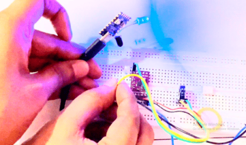
Testing
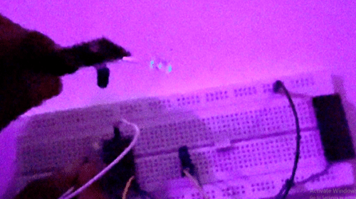
After the connections are properly made, press the piezo element hard such that the IR LED glows. The remote receiver circuit is brought close, and because of the piezo element being pressed hard, the IR LED glows and gives a signal to the IR receiver. This LED on the IR receiver (we have made and programmed) glows whenever the piezo element is pressed on the remote.
Thus, our batteryless remote is designed to work for years without any battery.
Also check the batteryless IoT Device.
Why you are using Solar cell for this concept why you are not going to vibrator charging concept
Yes we can also use that but the transducer is not available in local market for that
Yes we can also use that but the transducer is not available in local market for that