


 Different types of modulation techniques are used in telecommunication for transmitting and receiving radio frequency (RF) signals. With MATLAB tools we can analyse the modulation techniques used for these signals along with their mathematical representation. We can analyse carrier frequency parameters like amplitude, phase, and the frequency. Simulation with MATLAB tools helps us obtain the real-world characteristics.
Digital modulation is digital-to-analogue conversion (DAC) while demodulation or detection is analogue-to-digital conversion (ADC). The modulated digital signal can be transmitted through various media like cables, microwaves, or satellites. The following types of digital modulation techniques are simulated in this project:
- Phase shift keying (PSK): (a) binary phase shift keying (BPSK), (b) quadrature phase shift keying (QPSK), and (c) eight phase shift keying (8PSK)
- Amplitude shift keying (ASK)
- On-off keying (OOK)
- Quadrature amplitude modulation (QAM)
BPSK modulation
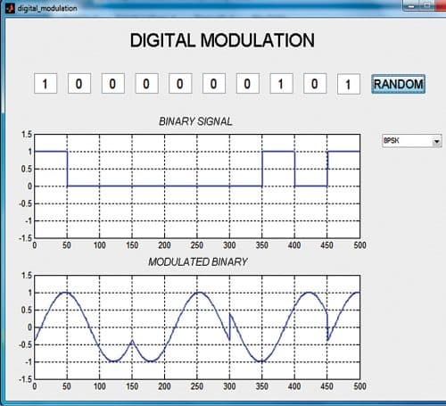
In PSK modulation, phase of carrier signal is changed in accordance with the input digital data. It is a digital modulation technique that is used for video, aircraft, and satellite signals. The most straightforward type of PSK is called Binary Phase Shift Keying (BPSK), where ‘binary’ refers to the use of two phase offsets (one for logic high, one for logic low).

That is, BPSK is a two-phase modulation scheme, where the 0’s and 1’s in a binary message are represented by two different phase states in the carrier signal: =0° for binary 1 and =180° for binary 0.
We can think of BPSK as simply inverting the carrier in response to one logic state and leaving it alone in response to the other logic state.
In BPSK modulation, the phase of the RF carrier is shifted 180 degrees in accordance with a digital bit stream (modulating input binary signal). A ‘1’ causes a phase transition, and a ‘0’ does not produce any transition. However, both peak amplitudes of the BPSK signals remain constant as phase changes.
Run the digital_modulation.m file and select the BPSK option from the drop-down menu on the right side of the screen. You will get the simulated output of BPSK modulated signal as shown in Fig. 1.
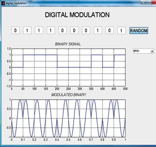
The incoming modulated BPSK signal is multiplied with carrier signal generated by the carrier generator. The output of the multiplier contains high-frequency and low-frequency components.
QPSK modulation
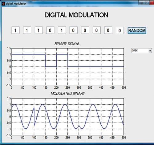
QPSK is a form of PSK in which two information bits out of 00, 01, 10, or 11 are modulated at a time, selecting one of four possible carrier phase shifts of 0, 90, 180, or 270 degrees. QPSK allows the signal to carry twice as much information as ordinary PSK using the same bandwidth. QPSK is used for satellite transmission of MPEG2 video, cable modems, videoconferencing, cellular phone systems, and other forms of digital communication over an RF carrier.
QPSK phase is changed in accordance with binary bits 1 and 0. The program output of QPSK modulated signal is shown in Fig. 2.
8PSK modulation
We can achieve bandwidth efficiency when we represent each signal element to map more than one bit. In BPSK modulation, digital data of 1 and 0 are represented by 180-degree phase change. Here, one bit per symbol is used. In QPSK modulation these are represented by phase shift of 90 degrees and so two bits are mapped on each signal. In multilevel PSK more than two bits are mapped using different phase angles. In 8PSK eight different phase angles are used where the incoming bits are encoded using three bits. Fig. 3 shows the simulation output of 8PSK signal.
ASK modulation
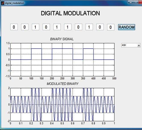
ASK is a type of amplitude modulation which represents binary data in the form of variations in the amplitude of a signal. Any modulated signal has high-frequency carrier signal. In ASK modulation, the level of signal amplitude can be used to represent binary logic 0’s and 1’s. Thus, logic 0 is represented by the lower level amplitude of carrier signal and logic 1 by the higher amplitude of carrier signal as shown in Fig. 4.
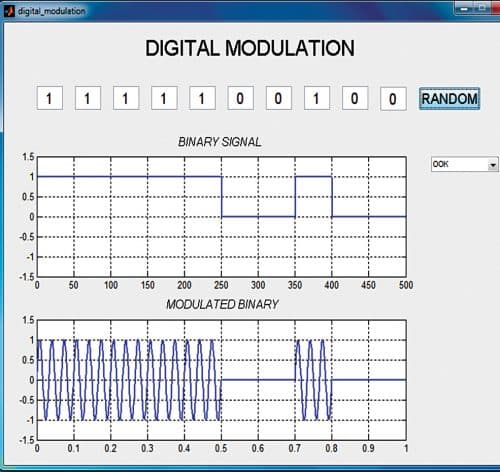
OOK modulation
OOK modulation is a popular technique used in control applications because of its simplicity and low implementation cost. It has the advantage of allowing the transmitter to idle during the transmission of a ‘0,’ thus conserving power. The disadvantage of OOK modulation lies in the presence of an undesired signal. As the proliferation of control and data communication apparatus increases, so does the aggravation of not being able to communicate.
OOK is a form of ASK modulation that represents digital data as the presence or absence of a carrier signal. We can think of carrier signal as an on or off switch. In its simplest form, the presence of a carrier signal represents a binary ‘1’ and its absence represents a binary ‘0’ as shown in Fig. 5.
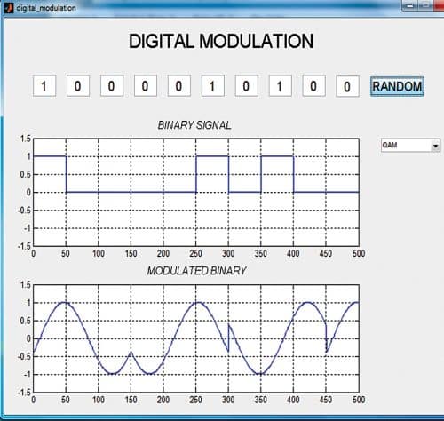
QAM modulation
QAM has been used for some analogue transmissions including AM stereo transmissions. QAM provides a highly effective form of modulation for data and is used in cellular phones and Wi-Fi systems.
QAM is a signal in which two carriers shifted in phase by 90 degrees (that is, sine and cosine) are modulated and combined. As a result of their 90° phase difference, they are in quadrature and hence the name. Often one signal is called the in-phase or ‘I’ signal and the other the quadrature or ‘Q’ signal. The modulated output waveform obtained from MATLAB simulation is shown in Fig. 6.
The resultant overall signal consisting of the combination of both I and Q carriers contains both amplitude and phase variations. In view of the fact that both amplitude and phase variations are present, it may also be considered as a mixture of amplitude and phase modulations. QAM is the name of a family of digital modulation methods and a related family of analogue modulation methods widely used in modern telecommunications to transmit information.
It conveys two analogue message signals, or two digital bit streams by changing (modulating) the amplitudes of two carrier waves. QAM is used extensively as a modulation scheme for digital telecommunication systems such as in 802.11 Wi-Fi standards. Arbitrarily high spectral efficiencies can be achieved with QAM by setting a suitable constellation size, limited only by the noise level and linearity of the communications channel. QAM is being used in optical fibre systems.
Download Source Code
Pankaj A. Raut is an electronics hobbyist. His interests include computer vision, robotics, optics, computational photography, and social computing.
Please note: If you are unable to download the source code, please try to open the page in incognito mode and retry or temporarily turn off the antivirus before downloading.
