


Presented here is a power-saving LCD backlight control circuit. An LCD is used in many projects for indication or information display since it consumes less power and, hence, saves energy. But power consumption in an LCD backlight draws a lot of attention.
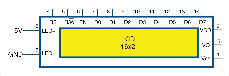
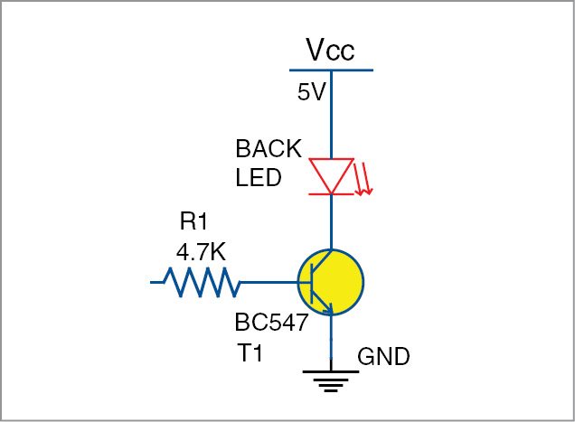
Pin diagram of a 16×2 alphanumeric LCD is shown in Fig. 1. Pins 15 and 16 are internally connected to the backlight LED. Normally, backlight LED+ is connected to +5V supply via a current-limiting resistor (it is not included in the circuit here for simplicity). But this LED stays on, all the time.
So if you want to dim it, you need a solution so that during daytime, or when ambient light is enough to make the LCD characters visible, the backlight gets dimmed and energy can be saved. For this, we have two options: one is microcontroller (MCU) based and the other is discrete-component based.
Circuit using an LCD is generally driven by an MCU. If the MCU has capture-compare pulse (CCP) width modulation module, our task becomes very easy. One such solution using a transistor is shown in Fig. 2. Here, CCP pin needs to be connected to the base resistor so that the LED can be dimmed. Then, we can use a light-dependent resistor (LDR) to sense the ambient light and command the MCU to dim the backlight accordingly.
If CCP pin is busy, or the MCU does not have a CCP pin, then an alternative circuit shown in Fig. 3 will ensure that the backlight is dimmed accordingly.
LCD backlight dimmer circuit
Circuit for dimming LCD backlight using NE555 is shown in Fig. 3. This NE555-based astable multivibrator generates output pulse frequency of 4.8kHz.
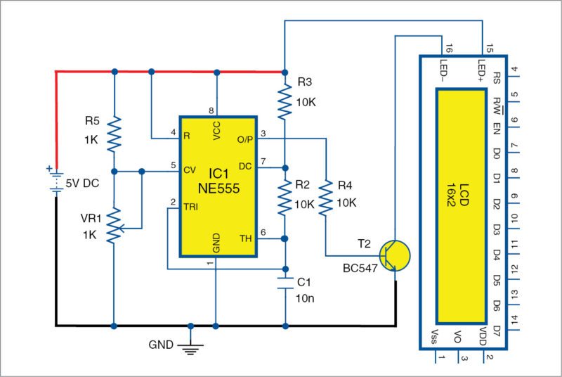
Note that control pin 5 is not grounded through a capacitor in the usual way, but is connected to a voltage-divider network formed by resistor R5 and VR1. This configuration makes it work as a pulse width modulator, which changes the width of output pulse at pin 3 based on the voltage at pin 5.
Potmeter VR1 can be replaced with an LDR so that the LCD automatically gets dimmed during day time. At night, or when ambient light is less, backlight intensity (current) increases.
Since LDR resistance changes as per ambient light, voltage at pin 5 of NE555 also varies accordingly. This variation in voltage at pin 5 changes the duty cycle of the output waveform, giving higher duty cycle when ambient light is not present, and vice versa. In this way it can be used to dim the LCD backlight for power saving.
So many error in this design.
Do not use.
1-You need a series resistor to limit the current in the LED
2-Add a series inductance to smooth the current from the source and to the LED.
3-R4 is too high for the HFE * current in this transistor BC547.
1-Series resistor is as such not required because the output of the 555 is a PWM, but we can put a series resistor , it is totally optional.
2-The current is in mili amps so it eliminates the use of inductor.
3-We have tested with same value of R4 at lab and on simulation software.
Also chances of improvements are always there in any design. I appreciate your enthusiasm of using the circuit and pointing out the mistakes of mine.
Thanks for your comments.
HAI,
Mr/Mrs/Miss – any one can help me how to control the “16×2 LCD” contrast using “PWM” signals in “ARDUINO” (ATMEGA 328P-AU)
i am waiting for YOURS possible reply………………………..
You can sense the ambient light with LDR change the duty cycle of the PWM accordingly
still u need a series resistor since that controls the maximum current. The PWM still pumps the as much current as the source can supply && circuit can sink, when transistors switched on. So, even at this time, u need a series resistor! Any way, thanks for writing this
Please read the text again, the same is mentioned in the text within brackets “(it is not included in the circuit here for simplicity).” Series resistor was used during testing at EFY Lab.