


This design’s applications are primarily focused on battery cell formation, test equipment, and programmable DC power supplies.
The dual-phase digital control battery tester is a crucial tool in battery technology, playing a vital role in ensuring the reliability and performance of batteries. This testing equipment utilises digital control to accurately evaluate battery parameters, such as voltage, current, and capacity, under various conditions. Its dual-phase approach allows for more precise and efficient testing, making it an essential instrument for battery manufacturers, researchers, and quality control professionals. The applications of this tester are diverse, ranging from developing and validating new battery chemistries to routine quality checks in production lines and diagnostic testing in after-sales service. It is widely used in automotive, consumer electronics, renewable energy, and aerospace industries, where battery performance and safety are paramount.
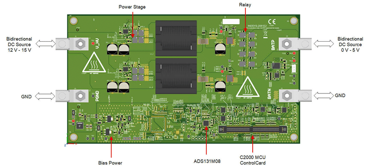
The reference design TIDA-010087 by Texas Instruments showcases a method for precisely controlling the current and voltage in a bidirectional interleaved buck converter power stage. This control is achieved using a C2000TM microcontroller (MCU) and a precision ADC ADS131M08. The design can maintain a current regulation error of less than ±20mA and a voltage regulation error of less than ±1-mV. This precision is attained by utilising the high-resolution pulse-width modulation (PWM) generation peripheral of the C2000 MCU.

The design has several key features that enhance its functionality and performance. These include a dual-phase interleaved 600-W bidirectional buck power stage and a PWM resolution of 15.8 bits at a 100-kHz switching frequency. It also incorporates an external delta-sigma ADC for closed-loop control. The design supports constant current charging and discharging with a regulation error of less than ±20 mA and constant voltage mode in both charging and discharging with a regulation error of less than ±1 mV. It is equipped with a software frequency response analyser (SFRA) and compensation designer to make it easy to tune control loops. PowerSUITE support facilitates easy design adaptation to meet user requirements.
The battery tester equipment associated with this design encompasses a wide range of equipment used to test single cells, battery modules, and high-voltage battery packs. This equipment includes precision power supplies and data acquisition systems and is used for charging and discharging batteries and measuring various cell parameters. The design offers a range of output voltage options. The minimum input voltage (Vin) is 12V, while the maximum input voltage (Vin) is 15V. The nominal output voltage (Vout) is set at 6V, with a maximum output current (Iout) of 100A. The design has an output power of 600W and is non-isolated. It operates with a DC input type and features a synchronous buck topology.
TI has tested this reference design, which includes a Bill of Material (BOM), schematics, test reports, PCB layout, and Gerber files. The company’s website has additional data about the reference design. To read more about this reference design, click here.
