


DC motors are widely used in industries to convert electrical energy into mechanical energy. The rotational movement of the motor shaft provides the power required for various applications like robotic vehicles, paper mills, and elevators.
A critical function of motor operation is speed control, which allows us to adjust the motor speed as per the application’s requirements.
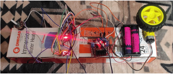
This guide explains the construction and operation of a DC motor speed control system using an Arduino Nano, L298 Motor Driver, and a seven-segment display.

Key Components of the System
1. DC Motor
A DC motor converts electrical energy (direct current) into mechanical energy. Its speed can be controlled by varying the DC voltage applied to it.
- Working Principle: Rotational motion is generated by transferring electrical energy.
- Speed Control Method: Achieved using Pulse Width Modulation (PWM) to apply a varying voltage.
2. Arduino Nano
The Arduino Nano is a compact, breadboard-compatible microcontroller board based on the ATmega328.

- Power Supply: Operates via Mini-B USB or an external source, automatically selecting the highest voltage.
- Features:
- 14 digital I/O pins (each capable of providing or receiving up to 40 mA).
- Operates at 5V with internal pull-up resistors.
3. L298 Motor Driver
A high-power motor driver module is suitable for controlling DC and stepper motors.
- Features:
- Built-in 5V regulator for external circuits.
- Controls up to four DC motors or two motors with speed and direction control.
4. 10K Potentiometer
A rotary variable resistor that controls parameters like motor speed.
- Specifications:
- Resistance: 10K ohms.
- Adjustable via a rotating knob.
5. Seven-Segment Display
An LED-based display is commonly used for numeric output in various applications.
- Type: Common Cathode Display.
- Functionality: Displays motor speed in RPM.
Parts List
- Arduino Nano
- L298 Motor Driver
- BO Motor (100 RPM)
- Common Cathode Seven-Segment Display
- 10K Potentiometer
- Wheels with Gearbox
- Breadboard
- Jumper Wires
- USB Cable
- Battery Holder
- 18650 Li-Ion Cells (3.7V, 2000mAh)
Circuit Design and Connections
- Potentiometer:
- Connect one pin to GND and another to 5V.
- Connect the middle pin to analog pin A1 of Arduino Nano.
- Seven-Segment Display:
- Connect pins a–g to Arduino Nano pins 13–7.
- Connect the decimal point pin through a 470-ohm resistor to the +5V pin.
- Common cathode pins are connected to GND.
- Motor Driver (L298):
- Pin 5 of Arduino Nano → Enable Pin A.
- Pin 3 and Pin 4 of Arduino Nano → IN1 and IN2 of the motor driver.
- Connect motor output pins to the BO motor and attach wheels to the gearbox.
- Power Supply:
- Use two 18650 Li-Ion cells (7.4V combined) to power the system.
Software and Programming
- Use Arduino IDE 1.8.19 for programming.
- The potentiometer sends an analog signal to the Arduino Nano, which adjusts the PWM signal to control motor speed.
- The seven-segment display outputs motor speed in RPM.
Testing the System
- Power the Circuit: Connect the 7.4V power supply.
- Verify Display: Ensure the display shows “0” initially.
- Adjust Speed: Rotate the potentiometer knob to vary speed:
- “0” → 0 RPM (minimum speed).
- “9” → 90 RPM.
- Single decimal point → 100 RPM (maximum speed).
- Observe Motor Behavior:
- Speed varies with knob rotation (0–255 on the PWM scale).
- Speed range: 0–100 RPM.
Applications and Future Enhancements
- Applications: Robotics, automation, elevators, and industrial machinery.
- Enhancements:
- Add LCD for more detailed speed monitoring.
- Extend to control multiple motors with directional control.
- Integrate wireless control for remote operation.
This project showcases a simple yet effective way to control a DC motor’s speed while providing real-time feedback.

Source Code
int seg_Pins[] = {13, 12, 11, 10, 9, 8, 7, 6}; // { a b c d e f g. )
int pot_map;
int pot_input;
////MOTOR1 PINS
int ena = 5;
int in1 = 3;
int in2 = 4;
byte seg_Code[11][8] = {
// a b c d e f g
{ 1, 1, 1, 1, 1, 1, 0, 1}, // 0
{ 0, 1, 1, 0, 0, 0, 0, 0}, // 1
{ 1, 1, 0, 1, 1, 0, 1, 0}, // 2
{ 1, 1, 1, 1, 0, 0, 1, 0}, // 3
{ 0, 1, 1, 0, 0, 1, 1, 0}, // 4
{ 1, 0, 1, 1, 0, 1, 1, 0}, // 5
{ 1, 0, 1, 1, 1, 1, 1, 0}, // 6
{ 1, 1, 1, 0, 0, 0, 0, 0}, // 7
{ 1, 1, 1, 1, 1, 1, 1, 0}, // 8
{ 1, 1, 1, 1, 0, 1, 1, 0}, // 9
{ 0, 0, 0, 0, 0, 0, 0, 1} // .
};
void setup()
{
pinMode(A1, INPUT);
pinMode(ena, OUTPUT);
pinMode(in1, OUTPUT);
pinMode(in2, OUTPUT);
for (int i = 0; i < 8; i++)
{
pinMode(seg_Pins[i], OUTPUT);
}
Serial.begin(9600);
}
void loop()
{
pot_input = analogRead(A1);
pot_map= map(pot_input, 0, 1023, 0 , 255);
//Serial.println(pot_input);
Serial.println(pot_map);
delay(300);
if ((pot_map > 1) && (pot_map <= 25))
{
digitalWrite(in1,LOW);
digitalWrite(in2,HIGH);
analogWrite(ena, pot_map);
for (int n = 1; n < 2; n++)
{
display_Digit(n);
delay(2000); ///2 second delay
}
}
else if ((pot_map > 25) && (pot_map <= 50))
{
digitalWrite(in1,LOW);
digitalWrite(in2,HIGH);
analogWrite(ena, pot_map);
for (int n = 2; n < 3; n++)
{
display_Digit(n);
delay(2000); ///2 second delay
}
}
else if ((pot_map > 50) && (pot_map <= 75))
{
digitalWrite(in1,LOW);
digitalWrite(in2,HIGH);
analogWrite(ena, pot_map);
for (int n = 3; n < 4; n++)
{
display_Digit(n);
delay(2000); ///2 second delay
}
}
else if ((pot_map > 75) && (pot_map <= 100))
{
digitalWrite(in1,LOW);
digitalWrite(in2,HIGH);
analogWrite(ena, pot_map);
for (int n = 4; n < 5; n++)
{
display_Digit(n);
delay(2000); ///2 second delay
}
}
else if ((pot_map > 100) && (pot_map <= 125))
{
digitalWrite(in1,LOW);
digitalWrite(in2,HIGH);
analogWrite(ena, pot_map);
for (int n = 5; n < 6; n++)
{
display_Digit(n);
delay(2000); ///2 second delay
}
}
else if ((pot_map > 125) && (pot_map <= 150))
{
digitalWrite(in1,LOW);
digitalWrite(in2,HIGH);
analogWrite(ena, pot_map);
for (int n = 6; n < 7; n++)
{
display_Digit(n);
delay(2000); ///2 second delay
}
}
else if ((pot_map > 150) && (pot_map <= 175))
{
digitalWrite(in1,LOW);
digitalWrite(in2,HIGH);
analogWrite(ena, pot_map);
for (int n = 7; n < 8; n++)
{
display_Digit(n);
delay(2000); ///2 second delay
}
}
else if ((pot_map > 175) && (pot_map <= 200))
{
digitalWrite(in1,LOW);
digitalWrite(in2,HIGH);
analogWrite(ena, pot_map);
for (int n = 8; n < 9; n++)
{
display_Digit(n);
delay(2000); ///2 second delay
}
}
else if ((pot_map > 200) && (pot_map <= 225))
{
digitalWrite(in1,LOW);
digitalWrite(in2,HIGH);
analogWrite(ena, pot_map);
for (int n = 9; n < 10; n++)
{
display_Digit(n);
delay(2000); ///2 second delay
}
}
else if ((pot_map > 225) && (pot_map <= 255))
{
digitalWrite(in1,LOW);
digitalWrite(in2,HIGH);
analogWrite(ena, pot_map);
for (int n = 10; n < 11; n++)
{
display_Digit(n);
delay(2000); ///1 second delay
}
}
else
{
for (int n = 0; n < 1; n++)
{
display_Digit(n);
delay(2000); ///2 second delay
}
}
}
void display_Digit(int digit)
{
for (int i = 0; i < 8; i++)
{
digitalWrite(seg_Pins[i], seg_Code[digit][i]);
}
}