

In 2023, we celebrate the International Year of Millets, honoring the nutritional richness and versatility of millets, such as Foxtail, Barnyard, Kodo, Little, and Brown-top varieties. These grains are known for their high dietary fiber content and diverse nutrient profiles.
To harness their benefits fully, it is vital to ensure minimal nutrient loss during cooking while achieving the desired softness for easy digestion.
Soak millets for at least four hours before cooking, focusing on one variety at a time to prevent overflow when using a pressure cooker.

Our solution: design a slow electric cooker that cooks nutritious, soft, and tasty millets perfectly.
POC Video Tutorial In English
POC Video Tutorial In Hindi
Components Required
| Parts List | |
| Semiconductors: | |
| IC1 | -CD4060 binary counter with a built-in oscillator |
| IC2 | -LM393 comparator |
| T1 | -BC558 pnp transitor |
| T2, T3 | -BC546 npn transitor |
| D1, D4 | -1N4007 rectifier diode |
| D2, D3 | -1N4148 signal diode |
| LED1 | -5mm white LED |
| LED2 | -5mm green LED |
| LED3 | -5mm red LED |
| IRF1 | -IRF540 mosfet |
| Resistors (all 1/4-watt, ±5% carbon): | |
| R1, R3 | -22-kilo-ohm |
| R2 | -390-ohm, 1-watt |
| R4 | -4.7-mega-ohm |
| R5-R7 | -1.2-mega-ohm |
| R8-R10, R21, | |
| R24 | -4.7-kilo-ohm |
| R11 | -1-kilo-ohm |
| R12, R16, R17, | |
| R22, R23, R25 | -10-kilo-ohm |
| R13 | -47-kilo-ohm |
| R14 | -3.3-kilo-ohm |
| R15 | -100-ohm |
| R18, R19 | -470-ohm |
| R20, R26 | -1-mega-ohm |
| VR1 | -2.2-mega-ohm potmeter |
| VR2 | -1-kilo-ohm potmeter |
| Capacitors: | |
| C1 | -1000µF, 63V electrolytic |
| C2 | -47nF ceramic disk |
| C3 | -0.47µF ceramic disk |
| C4 | -4700µF, 16V electrolytic |
| C5 | -0.1µF ceramic disk |
| Miscellaneous: | |
| PZ1 | -Buzzer |
| S1 | -On/off switch |
| S2 | -Push-to-on switch |
| CON1-CON4 | -3-pin connector |
| -AC to DC converter 48V, 2A | |
| -DC to DC converter XL7015 | |
| -Stainless-steel box | |
| -15mm copper wire 5mm dia | |
| -Heater coil (1800-watt) | |
| -Three small wooden battens | |
| -Teflon wires | |
| –Heatsink for IRF540 | |
| -10mm thick poly urethane foam | |
| -Thermistor | |
| -Nut, bolt, wire etc | |
| -Casserole with stainless steel surface inside (200mm dia× 80mm depth) | |
| -Banana clips (4) | |
| -3-leg heater support | |
| -Thermistor (10k NTC) | |
| -Three 18V, 30W solar panels (optional) | |
| -150 grams of millets | |
| -3-pin socket | |
This cooker is energy-efficient, keeping food warm due to thermal insulation, with cooking times ranging from 1 to 1.5 hours.
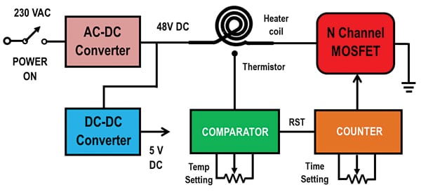
DIY Slow Electric Cooker – Block Diagram
The block diagram of the proposed cooker is shown in Fig. 1. It employs an 1800W electric heater coil powered by a 48V DC output from an AC-DC converter. An N-channel MOSFET controls the power supply to the heater.
The heater calculations are as follows:
- Resistance of heater coil= (230×230)/1800=29.4Ω
- Heat generated by coil=(48× 48)/29.4=78.4W
- Current through the coil=48/ 29.4=1.6A
Therefore, an AC-DC converter having a current rating of 2.3A is selected.
Two parameters determine the cooking time. The first is the heater temperature, which is monitored using a thermistor connected to a comparator circuit. The comparator trip point is set using a potmeter (VR2). This is a one-time setting. When the thermistor reaches the set temperature, the comparator enables the counter through an RST signal.
The second parameter is the user-controlled counter time setting. It works on setting the clock frequency to the input of the counter. Once the counter overflows, the MOSFET is turned off. The sum of both timings determines the total cooking time.
Having two parameters to determine cooking time offers flexibility. Temperature sensing accounts for the quantity of millet, allowing quicker heating for smaller quantities and longer times for larger ones.
The users can adjust the counter time setting based on their experience, providing control over the cooking process. This way a user has some control over the cooking time. These factors ensure that millets are properly cooked under all conditions.
Slow Electric Cooker – Circuit and Working
The circuit diagram of the millet cooker is divided into two sections.
The first comprises the power supply, counter, and MOSFET sections, and the second is the comparator and alarm sections. Fig. 2 shows the power supply, counter, and MOSFET sections.
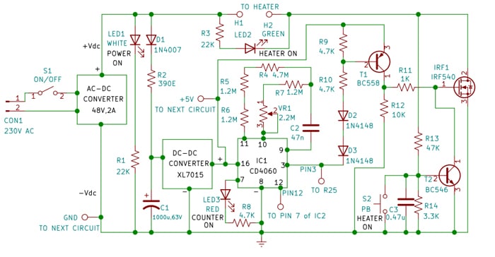
The input terminals of the AC-DC converter are connected to 230V AC through the on/off switch S1. The +Vdc output is connected to the H1 terminal of the heater coil. The H2 terminal is connected to the drain of IRF540. LED1 is connected to +Vdc through resistor R1, to indicate that the power is on.
The input terminal of DC-DC converter module XL7015 is connected to +Vdc through D1 and R2. Filter capacitor C1 helps to overcome very short disruptions in the 230V AC power supply. DC-DC converter output voltage is adjusted to get a +5V power supply.
The 14-bit binary counter (IC1) generates the user-controlled time period. It has a built-in oscillator with an adjustable frequency that is achieved through resistors and potentiometers.
Its pins 9, 10, and 11 are used to decide the oscillator frequency. Timing capacitor C2 is connected to pin 9. Pot VR1 is connected through series resistor R7 to pin 10. Resistors R4, R5, and R6 are connected to pin 11. Reset pin 12 is connected to the comparator output (pin 7 of IC2), as shown in Fig. 4.
When RST pin 12 goes low, the counter starts counting. Pin 3 (which is the 14th stage output Q13) of counter IC1 is initially low.
When the counter overflows, pin 3 goes high. To pin 7 (4th stage output Q3), red LED3 is connected through R8.
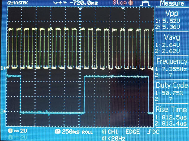
This pin toggles and LED3 keeps blinking, indicating that the counter is counting. Fig. 3 shows the oscillator waveforms at pin 11 (yellow) and pin 7 (blue). The measured time periods generated by the counter are as follows.
When the VR1 setting is minimum, the oscillator frequency will be around 7.35Hz. This means that the time period will be around 19 minutes and 12 seconds.
When the VR1 setting is maximum, the oscillator frequency will be around 2.53Hz. This means the time period will be around 53 minutes and 41 seconds.
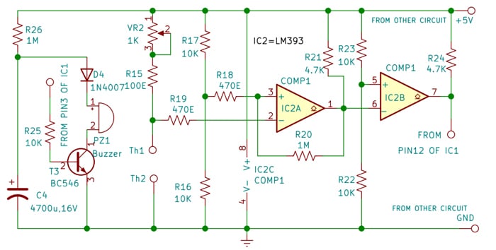
Fig. 4 shows the circuit diagram of the comparator and alarm sections. It uses dual comparator LM393(IC2).
To the non-inv pin 3 of COMP1, 2.5V is applied through the potential divider formed by resistors R16 and R17.
To the inv pin 2, the thermistor (10k NTC) is connected through terminals Th1 and Th2. The thermistor is powered through resistor R15 and potmeter VR2.
When the power is switched on, the voltage at pin 2 is greater than 2.5V because the thermistor is at room temperature (about 10k). COMP1 output at pin 1 is low.
COMP2 is configured as an inverting stage. Hence, the output at pin 7 is high. As the heater temperature increases, the resistance of the thermistor goes on reducing exponentially.
When resistance goes below R15 plus VR2, the COMP1 output goes high and the COMP2 output goes low. Pin 7 of COMP2 is connected to pin 12 (RST) of IC1, so the counter starts counting. Resistor R20 introduces hysteresis for preventing undesired switching.
Power-on sequence: Before turning on switch S1, ensure that the heater coil is connected to terminals H1 and H2. Similarly, connect the thermistor to terminals Th1 and Th2. When the power is switched on, MOSFET IRF1 is off, hence terminal H2 is at 48V. This voltage is applied to the base of NPN transistor T2 through a potential divider formed by R13 and R14. T2 is on and it pulls down the gate of MOSFET to the ground; it remains off.
To turn on the cooker, the user has to press the pushbutton S2. T2 turns off and MOSFET turns on. This is because, initially pin 3 of IC1 is low, hence PNP transistor T1 is on. Pin 3 of IC1 allows base current to flow through resistor R10 and diodes D2 and D3.
The green LED2 shows that the heater is on, connected between H1 and H2 with current-limiting resistor R3. As the heater warms up, the thermistor’s resistance decreases. When it falls below a threshold (< R15+VR2), COMP2 output goes low, triggering the counter IC1 to start counting. Once the user-set time elapses, the counter’s output at pin 3 goes high, turning off transistor T1 and the MOSFET.
In Fig. 4, an alarm circuit is included. It comprises an NPN transistor T3 with a buzzer (PZ1) connected to its collector. The base of T3 is linked to counter IC1’s pin 3 via resistor R25. When pin 3 of the counter goes high, T3 is activated. Capacitor C4 is gradually charged by R26 during the cooking phase. Capacitor C4 discharges through D4, the buzzer, and T3, causing the buzzer to sound until C4 is fully discharged.
Assembly and Testing
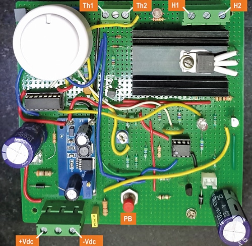
PCB Fabrication: Fig. 5 displays the PCB with labeled external connections. In the upper left corner, you will find the potentiometer VR1 with a white knob, which allows users to set the counter time.
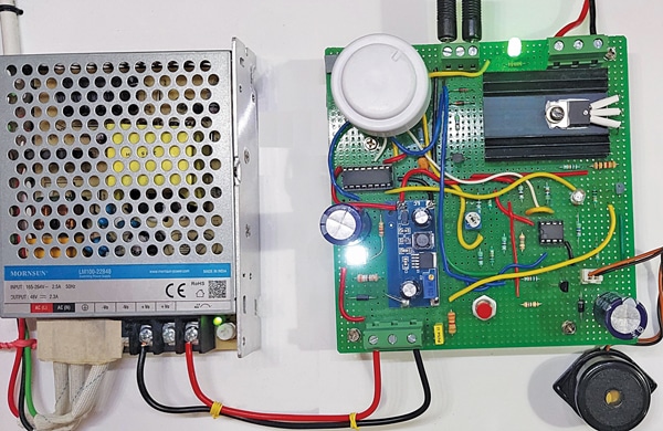
Fig. 6 displays the entire electrical system. The AC-DC converter is linked to the 230V AC mains supply via an unshown switch S1. Its output is connected to the PCB. The heater and thermistor are connected to screw terminals, while the buzzer is linked to the PCB through a 2-pin connector.
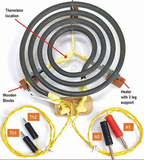
Heater Assembly: As shown in Fig. 7, the heater assembly comprises an 1800W heater coil and a thermistor. Choose a heater coil with three legs and attach three small wooden battens to these legs to minimize heat loss. Connect Teflon wires to the heater’s two terminals.
Mount the thermistor at the coil’s center on the leg support structure, connecting it with two Teflon wires. Exercise caution to shield all electrical joints from exposure to air; wrapping multiple layers of Teflon tape is recommended to ensure it remains secure during daily use.
Never heat the coil without a vessel placed on it. This cooker is designed for food items with water content or when water is added to the vessel. Using it for dry food items can harm the thermistor and other plastic components.
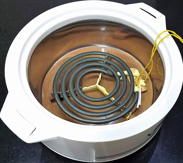
Fig. 8 shows the placement of the heater within the casserole with a stainless steel surface inside (200mm dia×80mm depth). Preferably keep a round piece of Teflon sheet below the heater coil.
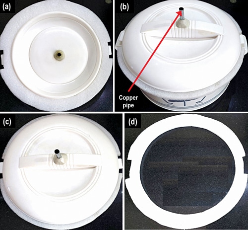
Cover Assembly: In Fig. 9, you will see the casserole cover assembly. In the centre of the cover, create a small hole and insert an 8mm diameter copper pipe. Secure the pipe permanently using Araldite to prevent steam from entering the insulated area inside the cover.
This pipe allows the steam produced during cooking to escape, preventing water buildup inside the casserole. Attach a 10mm thick Poly Urethane Foam (PUF) ring, as illustrated in Fig. 9(d), to the cover, as depicted in Fig. 9(a).
Place the soaked millets in a stainless-steel container. Add water, approximately 3 to 4 times the quantity of millets. Create a small hole in the container’s cover, as depicted in Fig. 10. This hole allows the steam, generated during cooking, to escape through the copper pipe in the cover.
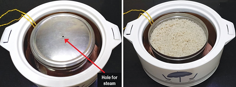
Usage: To cook, place the soaked millets and the required water in the stainless steel box. Put the box inside the casserole on the heater coil, ensuring the copper pipe aligns with the hole. Connect the heater coils to H1 and H2 terminals, and the thermistor terminals to Th1 and Th2. Adjust the potentiometer knob for the desired cooking time.
Switch on S1; the white LED lights up, but the heater remains off. To activate the heater, briefly press the S2 pushbutton. The green LED turns on, signifying the heater is running. At this point, the red LED remains off. After about 30 to 40 minutes, when the heater reaches the set temperature, the red LED begins to blink, indicating that the counter has started.
As time passes, steam gradually escapes through the copper pipe, and you can smell the cooking millets. When the counter overflows, the MOSFET switches off, and the green LED goes out. The buzzer sounds an alarm, signaling that the cooking is complete. If you need the cooked millets immediately, you can remove them, but if not, keep the cover closed.
In this state, the food will stay warm for one to two hours. Before opening the cover, remember to turn off S1, and use gloves or a kitchen towel as the box will be hot.
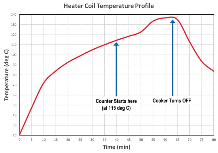
Fig. 11 depicts the coil temperature variation over cooking time, resembling an elephant curve. During the initial 0 to 10 minutes, the coil temperature rises rapidly. Within this period, only the coil heats up.
After 10 minutes, heat begins transferring to the box, causing a slower temperature to increase up to 50 minutes due to the large quantity of water present. Beyond 50 minutes, as the water in the box gets absorbed by the millets, the temperature rises again.
When the temperature surpasses 135°C, cooking is complete. This triggers the counter to overflow, and the MOSFET turns off. While the coil temperature decreases, the box temperature remains relatively high due to the insulation.
Energy Consumption:
Power consumed by the coil=78.4W
Efficiency of AC-DC converter= 95% (assumed)
Total power consumption=78.4/ 0.95=82.5W
Max cooking time=1 hr 30 min (assumed)
Energy consumed=82.5W×1.5 hrs=124Wh
Based on our calculations, it is evident that the proposed cooker is highly energy-efficient and does not consume power to maintain food warmth, potentially reducing energy costs. However, it has limitations, as it cannot cook tougher items like rice and dal.
It is best suited for soaking-dependent food types like millets and certain vegetables like beans and carrots.
The prototype has a capacity of about 150 grams of millets, with stainless-steel box dimensions of 170mm in diameter and 50mm in height. Increasing the cooking capacity can be achieved by using a box with the same diameter but a height greater than 50mm.
If the box touches the casserole cover, you can increase the PUF ring thickness to accommodate a taller stainless-steel box.
The proposed cooker requires a continuous power supply and is best suited for areas with infrequent power interruptions. In the event of a power outage during cooking, the user can resume by monitoring the steam from the copper pipe. When a steady stream of steam is visible, the cooking process is complete.
Since it is a low-power device, it can also be connected to a home inverter for uninterrupted power.
On a sunny day, the cooker can operate using three 30-watt power solar panels connected in series. Each panel should have a maximum power voltage (Vmp) of about 17.5 to 18 volts. Ensure that the PV panel output is connected to the +Vdc and -Vdc terminals, and make sure to disconnect the AC-DC converter output.
You can also set up a battery backup using four 12V lead-acid or lithium-ion batteries connected in series. Connect the battery output to the +Vdc and -Vdc terminals but be sure to disconnect the AC-DC converter output connections before doing so. These batteries, while expensive upfront, should have a longer lifespan since they will be used only occasionally.
Electrical Safety: The heater coil operates on 48V DC, which is considered a ‘safe’ voltage. When selecting an AC-DC converter, ensure it has mains supply isolation, typically achieved with an internal transformer (forward or flyback type). This design prevents the 230V AC mains from appearing at the converter’s output if it malfunctions. Always use a 3-pin socket and ensure proper grounding for added safety.
Thermal Safety: To prevent an unlikely circuit failure where continuous power to the heater could cause its temperature to exceed 150°C, it is advisable to include a thermal fuse in series with the coil. This fuse is mounted on the heater coil, similar to how the thermistor is placed. If the heater’s temperature surpasses 150°C, the thermal fuse will melt, cutting off the power supply to the coil. Please note that a melted thermal fuse should be replaced with a new one.
In the circuit diagram, the thermal fuse is not shown. In the absence of a thermal fuse, users should ensure that they turn off the switch once the cooking process is complete to prevent overheating.
This slow cooker is designed to preserve the nutrients and flavors of millets. It utilizes common heater coils and casseroles, making it straightforward to assemble and operate. It contributes to electricity savings and can run on solar power in bright sunlight.
If necessary, it can be linked to a home inverter or equipped with a battery backup. Widespread adoption of this appliance can enhance people’s health because it is common knowledge that millets are bullets of nutrients.
Dr. Vijay Deshpande has worked for more than 30 years as an electronics hardware engineer in several companies and recently retired from Honeywell India. He now likes to work on solar energy projects