

What does an electric vehicle charging controller handle beyond power? This design combines vehicle communication, safety monitoring, and connector control.
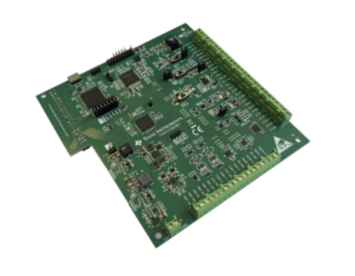
Designing an electric vehicle supply equipment (EVSE) controller requires functions beyond charging-power control. It must detect the vehicle, establish communication, control relays and locks, monitor temperature and safety signals, and exchange information with the power-conversion system. Texas Instruments (TI) combines these functions in the TIDA-010939 reference design, a front-end controller for AC and DC charging stations. It supports Combined Charging System (CCS) 1 and 2, North American Charging Standard (NACS), Guobiao/Tuijian (GB/T), and Charge de Move (CHAdeMO), giving engineers a starting point for charging systems supporting different vehicle and connector interfaces.
The design separates real-time vehicle-interface and safety functions from higher-level processing. A microcontroller handles front-end functions, while an application processor can run charging software. The two communicate over Universal Asynchronous Receiver Transmitter (UART). Engineers can pair the controller with an application processor evaluation platform, while an optional reference design adds an AC-to-DC power stage and relay interface.
The Control Pilot (CP) circuit provides communication between the EV and charging station. It generates a ±12 V, 1 kHz pulse-width modulated signal whose duty cycle communicates the available current during AC charging. A 5% duty cycle indicates that high-level digital communication is required. The EV changes the load on the CP line to indicate different states, allowing the EVSE to determine whether a vehicle is connected and whether charging can begin. The CP generator can source and sink at least 12 mA while maintaining rise and fall times below 2 µs.
An EV simulation circuit allows engineers to reproduce different charging states without connecting a complete vehicle, enabling CP behaviour and firmware testing during development.
For DC charging, the design uses HomePlug Green PHY (HPGP), the physical layer for ISO 15118 communication. The interface operates from 2 MHz to 30 MHz and supports data rates up to 10 Mbps. It connects to the application processor through Serial Peripheral Interface (SPI) and supports ISO 15118 functions such as authentication, Plug and Charge, and Vehicle-to-Grid (V2G) communication. GB/T and CHAdeMO use Controller Area Network (CAN) for high-level communication, so the design also includes a dedicated CAN interface.
The Proximity Pilot (PP) circuit detects cable connection and, with detachable Type 2 cables, identifies the cable’s current rating so the charging system can limit current accordingly. For Type 1 and NACS implementations, it can also detect the connector latch. The board supports different connector configurations through dedicated PP circuitry.
For safety and system control, the front-end controller monitors charging-contact temperature, controls a motorised plug-lock mechanism, and provides interfaces for residual-current detection (RCD). It has two 24-V-tolerant digital inputs, one 0–12 V analogue input, and three low-side digital outputs. The inputs can monitor safety switches and relay feedback, while the analogue input scales a 0–12 V signal to the 0–3.3 V range required by the microcontroller’s analogue-to-digital converter. The outputs can drive external loads such as relays and other charging-system actuators.
TI has tested this reference design. It comes with a bill of materials (BOM), schematics, assembly drawing, printed circuit board (PCB) layout, and more. The company’s website has additional data about the reference design. To read more about this reference design, click here.