In a switching power supply, sometimes the relay contacts fail due to a short-circuit, but the product continues to work. In the long run, this damages the device, especially because it is difficult to find the failure. Relays must be modeled correctly, and contacts must be chosen wisely to prevent such instances
All devices require a power source to work efficiently. Power supplies are devices that convert electric current from a source into the voltage required to power any appliance. A power supply can be of two types—linear or switching. For the scope of this article, we will be focusing on switching power supply and analysing certain failures that are associated with it.
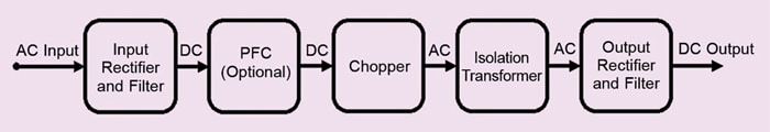
Despite being reliable, cost-effective, and ideal for low power applications, linear power supply has its disadvantages. Switching power supply design was developed to overcome these disadvantages and is comparatively a recent methodology. It uses switching devices that are turned on and off at high frequencies. This is why an electronic switch is one of the most fundamental components of a switching power supply circuit. The two most commonly used switching devices are the bipolar NPN transistor and the N-channel MOSFET. Furthermore, while the switching device is in its non-conduction mode, the switching power supply uses components such as inductors and capacitors to supply power.

Performance indices for switching power supply
Power factor
The power factor of an electrical or electronic device is the ratio of the power it draws from the main supply to the power it actually consumes. A gadget with a power factor of 1.0 consumes all of the energy it draws. It is possible to achieve a unity power factor, but many devices do not.
In the case of electronic devices, such as PCs and chargers that are driven by switching power sources, the power factor may be low because the device pulls current in a non-sinusoidal waveform. This is commonly referred to as the ‘distortion’ power factor, and it is very important to rectify it. If that is not done, the distorted power factor can cause unwanted harmonics.
Power factor correction
In a perfect system, 100% of the power drawn from the AC mains is put to good use. However, such a scenario is too good to be true. Due to the low power factor, some of the energy from the AC source is not utilised and is lost. This increases cost and contributes to global warming too. Hence, power factor correction (PFC) is done to increase the power factor.
PFC can be done in two ways:
First, passive PFC, which improves PF by utilising passive filters to filter out harmonics. This is commonly used in low-power applications. However, it is insufficient in high-power applications.
Second, active PFC, where a switching converter is used to modify the distorted wave into a sine wave. Because the new signal’s sole harmonics are at the switching frequency, these can be easily filtered away. This is a good approach, but it adds to the design complexity.
Input inrush current/Surge current. When you turn on a power source or electrical equipment, it generates a temporary current called inrush current. This is due to the high initial current needed to charge the capacitors, inductors, and transformers. The inrush current is also known as the switch-on surge or input surge current. It is an important performance indicator for switching power supplies.
In the case of a switched-mode power supply (SMPS), the output capacitor, which is normally big in value, can hold a huge amount of charge that is comparable to a short-circuit when not energised. The switches in the SMPS link the input source to the empty capacitor when an energy source is attached to the SMPS. This creates a low impedance path for the inrush current to flow to the capacitor. The voltage across the capacitor rises, but slowly decreases thereafter. That being said, the inrush current is large enough to damage the switches in the supply circuit, and hence needs to be designed as small as possible.
To control the inrush current, a ‘pre-charging’ circuit may be used. The conventional design is to connect a thermistor (NTC) in series on the live wire at the input of the switching power supply. For switching power supply with a higher power, a relay is connected in parallel to the thermistor (NTC) at the same time to reduce device loss and improve reliability when the product works normally.
Let us now focus on analysing the causes of contact short-circuit failure after incorporating the relay.
Finding the fault
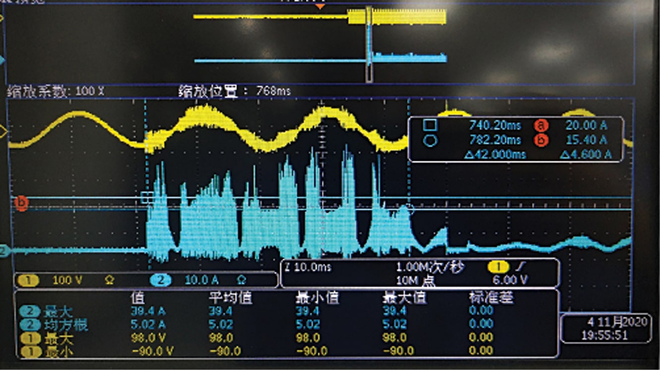
When the PFC circuit in Fig. 2 was applied to the product, it was found that the inrush current exceeded the standard value. This result was completely different from the theoretical calculation. According to Fig. 2, the devices that affect the input inrush current are mainly the thermistor RT1 and relay K1.
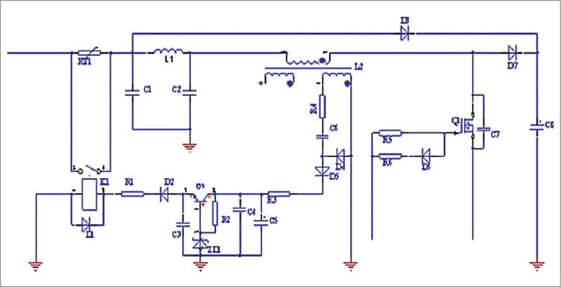
After testing the thermistor and relay it was observed that the thermistor resistance is normal, and the normally open contact of the relay is taken in (sucked) without a power supply. This means that the relay is the abnormal device here.