


The popularity of electric vehicles (EVs) is increasing rapidly in India. According to a survey, the EV market in India is estimated to increase from 3 million units in 2019 to 29 million units by 2027 with a CAGR of 21.1%. As a result, demand for AC/DC chargers and smart EV chargers will also increase.
In order to charge the batteries efficiently and to ensure their long life, we need smart battery management or charging system. To realize such EV charging stations, Holtek has come up with smart Electric Vehicle Battery Charging Solutions based on their low-cost ASSP flash microcontroller (MCU) HT45F5Q-X for charging EV batteries.
At present, three EV charger designs suitable for the Indian market with specifications of 48V/4A, 48V/12A, and 48V/15A are available for rapid development of the product. This semiconductor-based smart charging system can support both lithium-ion as well as lead-acid battery types.
EV Charger Block Diagram
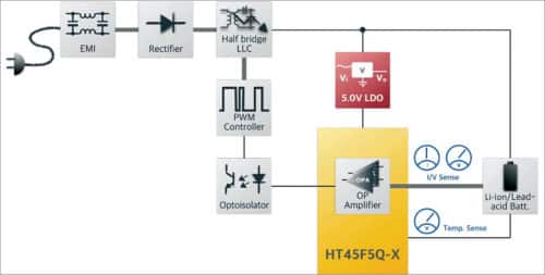
The Block diagram of the Electric Vehicle Battery Charging Solution is shown in Fig. 1. Here, battery charger ASSP flash MCU HT45F5Q-X is the heart of the EV charger circuit with in-built operational amplifiers (OPAs) and digital-to-analog converters (DACs) that are necessary for battery charging function.
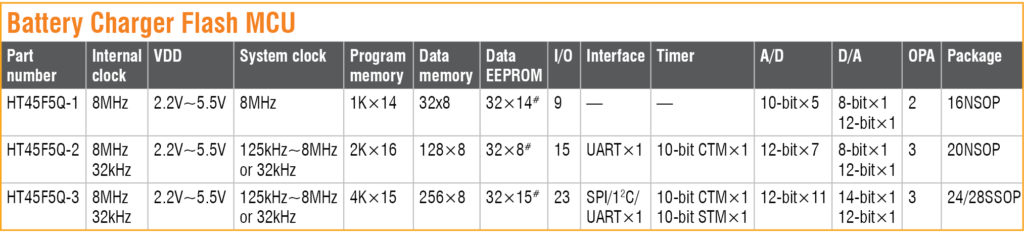
Designers can choose an appropriate MCU from the HT45F5Q-X series according to their application requirements.
Specifications of the battery charger flash MCU HT45F5Q-X series are shown in Fig. 2.
The features and working of the EV charger solution for 48V/12A specification are briefly explained below. This EV charger design utilizes HT45F5Q-2 MCU for implementing the battery charging control function.
The MCU incorporates a battery charging module, which can be utilized for closed-loop charging control with constant voltage and constant current for efficiently charging a battery. The internal block diagram of MCU HT45F5Q-2 is shown in Fig. 3.
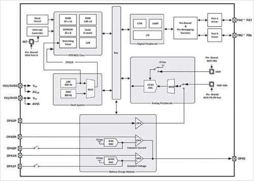
The battery charging module in HT45F5Q-2 has built-in OPAs and DACs that are needed for the charging process. Therefore the design reduces the need for external components like shunt regulators, OPAs, and DACs, which are commonly used in conventional battery charging circuits. As a result, the peripheral circuit is compact and simple, resulting in a smaller PCB area and a low overall cost.
EV Charger Working
Input power to the EV charger is an AC voltage in the range of 170V to 300V. The EV charger uses a half-bridge LLC resonant converter design, because of its high-power and high-efficiency characteristics, to obtain DC power for charging the battery.
The design utilizes a rectifier circuit for converting input AC voltage to high-voltage DC output, and it also has an electromagnetic interference (EMI) filter to eliminate high-frequency noise from the input power source. A pulse-width modulation (PWM) controller IC, like UC3525, can be used for driving the MOSFETs of the half-bridge LLC converter.
The battery charging process is supervised by the MCU HT45F5Q-2. It monitors the battery voltage and charging current levels and gives feedback to the PWM controller IC. Based on the feedback, the PWM controller varies the duty cycle of its PWM signal and drives the MOSFET circuit to obtain variable output voltage and current for charging the battery.
For better protection, HT45F5Q-2 is isolated from the rest of the circuit (i.e. high-voltage components) using a photo-coupler. Battery-level LED indicators are provided for knowing the charging status.
EV Battery Charging Process
The change in charging voltage and current during the charging process is graphically illustrated in Fig. 4. If the battery voltage is too low when connected for charging, low charging current (i.e. trickle charge (TC)) will be set initially, and the charging process will start.
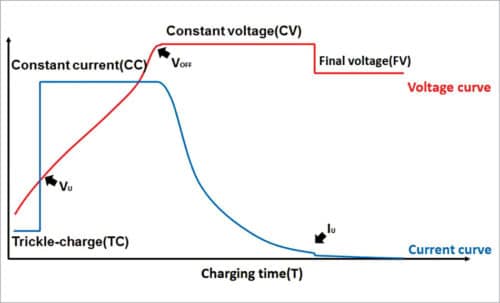
When the battery voltage increases to a pre-defined level (Vu), constant voltage (CV) and constant current (CC) are applied for charging and continued until the battery is fully charged. The battery is considered to be fully charged when the voltage reaches VOFF. When the charging current drops to Iu, the final voltage (FV) is set.
The voltage, current, and temperature control processes in this EV charger are explained below.
(a) Voltage Control
The charging voltage is decided based on the initial voltage of the battery when it is connected for charging. As the charging progresses, the charging voltage changes accordingly, and finally, when the battery is fully charged, the final voltage is set. The charging-voltage decision levels for the 48V/12A battery charger are explained below.
- If Battery Voltage <36V, TC(0.6A) Charging, Voltage Setting FV(56V)
- If Battery Voltage <40V, TC(0.6A) Charging, Voltage Setting CV(58V)
- If Battery Voltage >40V, CC(12.0A) Charging, Voltage Setting CV(58V)
- When fully charged, the voltage is set to FV(56V). If the battery voltage is lower than FV, the charging current will be reset to CC (12.0A).
(b) Current Control
The charging current is set depending on the battery voltage. Initially, if the battery voltage is too less, a trickle-charge current would be set for charging the battery. Once the battery voltage reaches a certain level, a constant current is supplied for charging, until the battery is charged fully. The charging-current decision levels for the 48V/12A battery charger are listed below.
- Recharging Current <1.2A, determine the end of charging
- Recharging Current >0.2A, determine the start of charging
(c) Over-temperature Protection
The EV charger has a negative temperature coefficient (NTC) thermistor to monitor the temperature and a fan to regulate the heat. When the temperature increases, the fan is automatically switched on to dissipate the heat; it gets switched off when the temperature is reduced to the lower set threshold. Also, the fan turns on when the charging current is high and turns off when the charging current is low.
- When NTC temperature >110°C, the charging current will be reduced to 50% of the charging current and will be monitored periodically
(d) LED Indications for Charging Status
These are listed below-
- TC charge, red light flashes slowly (0.3 sec on, 0.3 sec off)
- CC, CV charge, red light flashes quickly (0.1 sec on, 0.1 sec off)
- When not charging, the green light is on
- When charging time exceeds eight hours, red and green lights are bright
(e) Charging Duration
When the charging duration is exceeded (duration depends on battery capacity), the voltage drops to FV, the current is reduced to TC, and the charger repeatedly monitors the battery voltage.
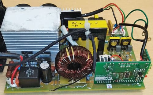
EV Charger Circuit Diagram
The schematic of the Holtek EV charger design for 48V/12A type is shown in Fig. 5 for reference and its PCB assembly is shown in Fig. 6.
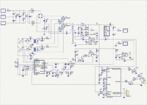
Check High-Resolution Image
The ASSP flash MCU HT45F5Q-2 can also be used for designing higher-wattage solutions. It offers a programmable option for setting parameter thresholds, which makes it very convenient for EV charger designs. Holtek provides technical resources such as block diagrams, application circuits, PCB files, source code, etc. to help designers in rapid product development and speed up time-to-market.
EV charger development platform for the HT45F5Q-X series will also be available soon. Using this software tool, users would be able to easily select the charging voltage/current and other parameters to create a program. This application will also be able to generate a program containing a standard charging process, thereby significantly simplifying the development process.
Krishna Chaitanya Kamasani is the director – India operations at Holtek Semiconductor

I also worked on battery charging with ,24v alternator runnig with motor iwas getting 28v with 1800 rpm which I put on two wheeler vehicle for mr leon who apporach to me for vehicle charging in running
Hello sir can u explain about this process
Mob ( 9353090235) watsap
Sir i want to built a EV charger that can delivers 48V,12A output,but in the circuit diagram components values are not given.plz send a circuit diagram that has all the component values.
The hex file for the microcontroller
Any update about the .hex?
Sor
The average capacity of the EV battery is 32 KVA. May you provide circuit diagram and details for 32 KVA battery. And also for on board (in vehicle) circuit diagram. I shall be very much thankful for your kind deed please.
Can the circuit be modified to charge Lithium battery of E-rickshaw from 90 V solar panel at roof to boost range of travel ? If yes, please share circuit idea and codes.
Sir,
I am also in a startup to design Battery array charging circuit for EV batteries (Li-ion)
Request you to share the Circuit diagram with component list and quotation of the same.
Hello Amit: Did the start-up go well? Please email me to [email protected].
Best regards,
I got a plan I can run electric car without a battery was some that would take interest in it
Kindly share an email to [email protected].
I want Develop EV charger please provide me right solutions.
Kindly elaborate your query.
I need the simulation file…how can I get it??
Did you get it?
Where can I get Reference design and code?
Hello there – Anyone here building L2 7.2KW 208V-240V 30A EV charging stations? I am seeking for a provider.
Email to [email protected]
Best regards, Randall Marín
Dear sir,
I am having charging problem with Mahindra EV Model e2o, 2016. It stopped charging and says “Turn on mains” on the display. From AC input to DC rectification is fine (291V DC). 48V DC to 12VDC conversion is also working perfectly BUT 220V DC to 48V DC is not working. I got advice to change charger unit and I did do it. The new charger worked for 6 days and again come out the same message and stopped charging. I took the vehicle to Manindra Servcice station here in Kathmandu. We install again new charger and it worked for 2 days and started the same message and stopped charging. So far it has eaten up 3 chargers which were very costly for me. Manindra Servcice station here in Kathmandu also could not solve the problem yet. If you or anybody from Mahindra or other EV experts in India suggest me a solution to get my e2o run, I would be grateful to them. It has been in the garage since last 7 months. Thank you for your cooperation.
Hello sir Im interred for develop ev charge controller if u can support me pls contt. if possible.
I wanted to develop a 3KW EV charger. Nominal 48V 50A.
Sir I need Technologies transfer for the charger 54v40 anp, kindly call me 9940039638
Kindly elaborate on your query.
We are in the field of electrical panel (all types) manufacturing, we are interested to add EV Charger manufacturing business in our plant.
Anyone have simulations and gerbar file
Kindly shere your contact details dear site creator
Looking for a resource who can help build EV charger prototype either full time/part time basis. Anyone interested pls write to me [email protected]
hi,
u need any help for part time in automotive hardware design.
Sir great. I am working in EV Sector since 2 years. Please provide me Contact & Address Details to Order This Charger for my customers.
Can you please share the components name, its values and simulation software used to design this?
I am developing a charger with GaN mosfet, can i get the specifications and schematics for 48v 15 amp charger
Any article or design employing microcontroller is totally useless without the well commented source code. EFY editorial team should explicitly ask for the source code before publishing such articles. If the author is not willing to share the source code then EFY team should not publish it.
Thanks,
I have a start-up company we want to expand in the ev fast charging buissness so we need to develop our own ev dc fast chargers (more than 50kwh) can you provide the schematics and circuit designs for the same it will be of great help
Dear Dewan,
We do not have circuit diagram of ev dc fast chargers (more than 50kwh)
as it is a very special designing.
Sorry for that.
Regards
I want to manufacture 60 kw DC fast chargers with dual gun in india. Can I get complete technical know how and manufacturing facility setup consultancy
Dear Sir,
Are you giving design and manufacturing consultancy for EV charging equipment manufacturing like 40 kw , 60 kw, 100kw etc..If so I would like to discuss further on that .
Lawrence