


By understanding the basics of the powerful little Peltier modules, you can better choose the right-sized module with performance ratings to adequately support the thermal management requirements of your design.
Sometimes cooling needs to be controlled more strictly than a simple heat-sink and fan can handle. Rapidly fluctuating loads can make it difficult to keep a component cool and stable. However, this can often be important when trying to improve signal-to-noise performance or prevent damage to a system.
On the other hand, reliability calculations may require a controller or power component to operate below normal ambient temperature. Non-electronic applications, such as controlling the rate or performance of a chemical reaction, also require precisely managed cooling.
Fortunately, there is a solution to help you tackle tough challenges like these. Thermoelectric modules, or Peltier modules, are available in a variety of sizes that can be connected to an IC package or other types of components in a manner similar to a heat-sink.
Powered by a small current, the module actively draws thermal energy from the attached heat source and dissipates it into the atmosphere. It can be designed to keep the component cooled to a specific temperature, or even below room temperature, if necessary.
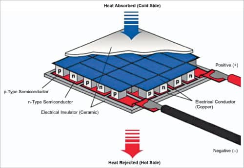
A Peltier module comprises two external ceramic plates separated by a series of PN-doped semiconductor pellets that are electrically connected in series. When current passes through the matrix, a temperature gradient is established according to the Peltier effect.
This causes one of the module’s boards to cool down, allowing it to absorb heat from a source (such as the surface of a component, such as a chip or laser diode), while the other side becomes hotter, and thus, it can dissipate heat into ambient air or a heat-sink. This allows heat to be efficiently extracted from an attached component, as long as both the extracted heat and that internally generated by the operating current can be dissipated on the opposite surface.
Design of a thermoelectric cooling system
Note that the Peltier element cannot absorb heat. It is purely a transfer mechanism. Therefore, it is essential to dissipate heat from the hot surface. To start designing a system that cools a component to the desired shell temperature, we need to know a few key parameters:
- Desired temperature of cold side of module
- Temperature difference across the module
- Module’s hot side temperature
- Module surface
- Required operating current
- Required driving voltage
The data sheet for a Peltier module specifies the difference in temperature (T) measured on the outer surfaces of the outer ceramic plates of the module. A thin layer of thermal interface material (TIM) should be inserted where the module adheres to the component and the heat-sink, so the effects of these should be considered when designing the system.
Knowing the hot side temperature is necessary because the characteristics of the Peltier module change with its operating temperature. CUI Devices datasheets specify module performance at various temperatures to help designers optimise the system.
Even so, the temperature required for the application is unlikely to exactly match one of those in the datasheet. So, the designer should look at the curves for the closest temperature to understand how the module will work in practice.
The surface of a Peltier module must be similar to that of the heat source. A large mismatch can be compensated for by using a heat spreader. The spreader is generally made of aluminium or copper.
Like an LED, thermoelectric modules are a current-driven device. The simplest way to achieve the desired performance is to drive a Peltier module with a controlled current source that has sufficient compliance to provide the required load voltage. This can be determined from the module data sheet and operating restrictions.
As an example, let’s use a generic Peltier module to demonstrate the design of a thermoelectric cooling system where the required heat transfer, surface temperatures, and surface area of the object are known.
Assuming:
- 20W heat transfer through module
- 20°C temperature difference across the module
- 30°C hot side temperature
- 30×30mm object surface area
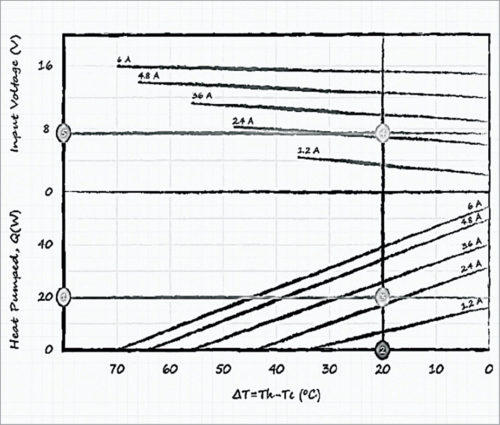
The curves of thermal energy versus temperature and input voltage versus temperature are used to calculate the operating current and voltage.
Draw a horizontal line at 20W on the heat pump axis, representing the power transferred through the module.
Draw a vertical line at 20°C, that is, the temperature difference maintained throughout the module.
The two lines intersect at approximately 2.7A. This is the current required to operate the module.
Mark where the vertical line intersects 2.7A on the input voltage graph.
This corresponds to approximately 7.5V, which is the required voltage compliance of the current source.
Operating at 2.7A and 7.5V, the power consumption of the module is 20W. Therefore, the total heat dissipated by the heat sink is 40W (20W heat source + 20W heat-sink module).
As an alternative to conventional cooling with a directly attached heat-sink, the use of a thermoelectric or Peltier module can ensure greater precision and temperature stability thanks to a faster transient response, while the latest advances in semiconductors allow the modules to stay reliable and profitable.
By understanding the basics of these powerful little devices, you can better choose the right-sized module with performance ratings to adequately support the thermal management requirements of your design.
Jawaaz Ahmad from Srinagar is a Design Fellow at Design Innovation Centre, Islamic University of Science and Technology, Awantipora
