


 Use of a room heater at night in winters can cause sleepless nights, dry skin, and allergy. Worse, it can prove a health hazard due to increase in level of carbon monoxide in the room. People with heart disease may get chest pain, and smokers with heart disease are at even greater risk.
This happens because the room heaters deplete the quantity of moisture present in the air and make it dry. So, people who are already suffering from respiratory diseases can feel suffocated when these heaters are used for a long time.
Room heaters also consume lots of electricity, unnecessarily, when not required, as these have high wattage rating. This simple but useful circuit can help avoid all such issues. It can control up to two heat convectors.

Circuit and working
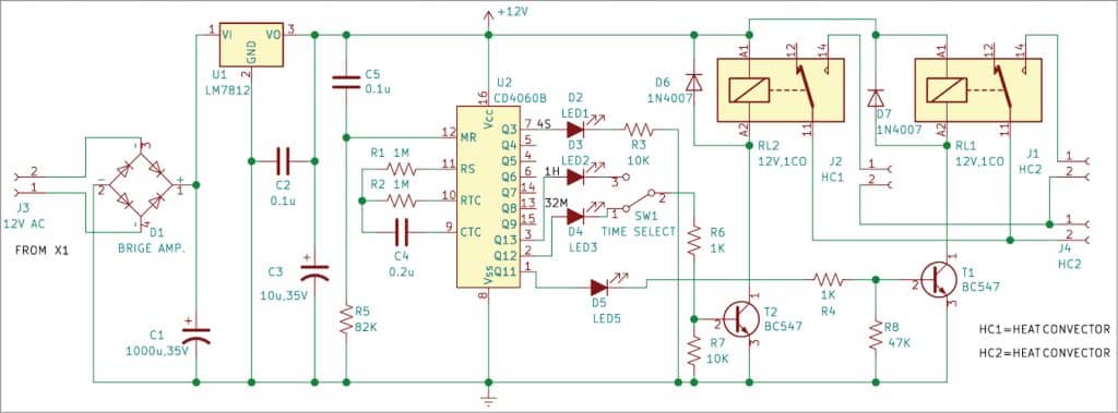
Fig. 1 shows block diagram of the energy saver circuit for heat convectors. Fig. 2 shows the complete circuit diagram comprising a power supply and timer for heat convectors HC1 and HC2.
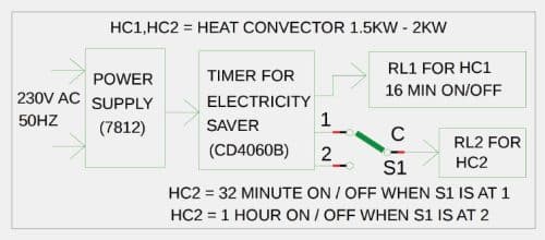
Connect HC1 across relay contacts of RL1 to switch it on for about 16 minutes and then switch off for next 16 minutes. Similarly, connect HC2 across relay contacts of RL2 to switch on for about 32 minutes and then switch off for next 32 minutes, provided switch SW1 is at position 1. If switch SW1 is at position 3, on/off time of HC2 will be one hour.
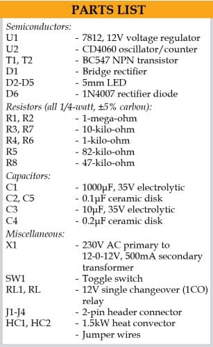
The energy saver is built around a step-down transformer (X1), 12V regulator 7812 (U1), counter/oscillator CD4060B (U2), four 5mm LEDs (LED1 through LED4), four 1N4007 diodes (D1 through D4), two 12V single-changeover relays (RL1 and RL2), and a few other components.
IC CD4060 requires external timing components to feed oscillations to the clock at pin 11. The timing capacitor is connected to pin 9 and the timing resistor to pin 10. With timing components, resistor (R1) and capacitor (C4), U2 oscillates and provides delay outputs based on the values of the components.
Pin 12 of the IC is the reset pin. IC oscillates only if the reset pin is at ground potential. So, a 0.1µF capacitor and 82-kilo-ohm resistor are connected to reset the IC at power on to start oscillation.
The IC has ten outputs, numbered Q3 through Q13 (with Q10 missing), each of which can source around 10mA current at slightly less than Vcc voltage. Output Q10 is not used so that double time can be obtained from Q11. Each output from Q3 through Q13 goes high after completing one timing cycle. The maximum time is available at the last output Q13. But during that time, others also give high outputs based on their timing.
The circuit uses only four outputs: Q3 (pin 7), Q11 (pin 1), Q12 (pin 2), and Q13 (pin 3). Output pin 7 is used to flash LED4 for indicating that the circuit is oscillating. Output pin 1 is used to connect heat convector HC1 via relay driver transistor T1. LED1 and R4 are connected to the base of T1. Pin 1 will be high for 16 minutes and then low for 16 minutes, and the cycle will keep repeating. Accordingly, HC1 will be on for 16 minutes and off for 16 minutes. Glowing of LED1 means HC1 is on.
Similarly, output pins 2 and 3 are used to connect HC2 via switch SW1 and relay driver transistor T2. LED2 and LED3 are connected to the base of T1 via series resistors R5 and R6, respectively. Pin 2 goes high for 32 minutes and low for next 32 minutes, provided switch SW1 is at position 1. Thereafter the cycle repeats. Accordingly, heat convector HC2 is on for 32 minutes and off for 32 minutes. Glowing of LED2 means HC2 is on.
Pin 3 goes high for one hour and low for next hour, when switch SW1 is at position 3. Thereafter the cycle repeats. Accordingly, heat convector HC2 is on for an hour and off for the next one hour. Glowing of LED3 means HC2 is off.
The time periods are governed by the relationship:
The basic frequency
fosc=1/2.5 (R1xC4) in Hertz
Where R1 is the resistance at pin 10 in ohms and C4 the capacitance at pin 9 in Farads. For example, if R1 is 1-mega-ohm and C4 is 0.22µF, fosc is 1/2.5 (1,000,000×0.000,000,22) =1.8Hz. If the selected output is Q3, then 2n is 23=8. Therefore, time period (in seconds) is t=2n/1.8Hz =8/1.8=4.4 seconds.
When both HC1 and HC2 are on for 12 hours using this circuit, the convectors will be on for only half the time, that is for just 6 hours each day. So, the power consumed by HC1 and HC2 per day will be just half.
Construction and testing
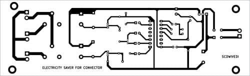
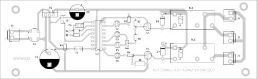
An actual-size PCB layout for the energy saver for heat convectors is shown in Fig. 3 and its component layout in Fig. 4. After assembling the circuit on PCB, enclose it in a suitable plastic box. The connectors for HC1 and HC2 convectors should be fixed on rear side of the box.
Download PCB and Component Layout PDFs: click here
S.C. Dwivedi is a Lab Engineer at EFY
Good morning,
what exactly relay model you used (fitting with dimensions to footprint on PCB) in this project ?
Description “12V single changeover (1CO) relay” gives to many possibilities to find.
Sincerely,
Paul
PS1 There is mistake on PCB, C5 should be connected to +5V but is connected to GND (now is parallel to R5).
PS2. Please, give more exact info about parts in articles because manufacturers doesn’t sleep and continously “invents” new models of parts that there is problem in finding specific element.