


 Fastest finger first system are used in school, college and TV contests. The team which presses their push-button switch first is entitled to answer the query. When two or more teams press their push-buttons within a very small time gap, it becomes very difficult to identify the team that pressed the button first. In such cases, the decision can be biased due to human intervention.
The system presented here takes care of the aforesaid problem. This system can be used for a maximum of four teams in its present form. It is built around a Raspberry Pi board and a solid-state relay module.
Circuit and working
The Raspberry Pi runs a standard Raspbian Linux distribution with Wi-Fi dongle, installed GPIO library and software written in Python. Most of the coding has been done on the Raspberry Pi. Indicator bulbs are provided on contestants’ desks to know who pressed the push-buttons.


The HDMI output is connected to an LCD monitor to know the sequence of buttons pressed by the teams if two or more teams press the buttons almost simultaneously. The circuit can also be controlled via an SSH connection using VX ConnectBot software on an Android smartphone.
You may refer previous EFY issues for installation of standard Raspbian Linux distribution. Installation guide for Wi-Fi dongle on Raspberry Pi varies from dongle to dongle, so you may check it on Google.
Raspberry Pi GPIO library can be installed using following commands on the terminal window:
$ sudo apt-get install python-rpi.gpio
or
$ sudo apt-get install python3-rpi.gpio
To access the above libraries add following lines to the Python script (rasquiz.py):
import RPi.GPIO as GPIO
GPIO.setmode(GPIO.BOARD)
termcolor module is used for simple formatting of text to colour, make bold, underline, highlight, etc. Install termcolor using command given below:
$ wget http://pypi.python.org/packages/
source/t/termcolor/termcolor-1.1.0.tar.
gz
$ tar -xvzf termcolor-1.1.0.tar.gz
$ cd termcolor-1.1.0
$ sudo python setup.py install
Please refer the link below for more detail.
https://pypi.python.org/pypi/termcolor
Download VX ConnectBot software from Play Store on Android smartphone. Start tethering or hotspot on smartphone and connect Raspberry Pi to it over a Wi-Fi network. After that start VX ConnectBot software and login to Raspberry Pi over SSH connection using pi@ and default password (in this case raspberry). A terminal window will open on your Android phone from where you can run the Python script.
The input push-button switches (S1 through S4) are wired such that when pressed, its one end gets connected to GND (pin 9). The input pins are pulled up (internally) to 3.3V by the optional argument:
pull_up_down=GPIO.PUD_UP in GPIO.setup
This means that, when you read the input value using GPIO.input, ‘False’ will be returned if the button is pressed. Each GPIO pin has software configurable pull-up and pull-down resistors.
The event_detected( ) function is designed to be used in a loop with other things, but unlike polling, it is not going to miss the state change of an input while the CPU is busy working on other things. This could be useful in something like a quiz game where there is a main loop listening and responding to GUI events on a timely basis. For example, falling-edge detection on a channel can be written as:
GPIO.add_event_detect(channel, GPIO.
FALLING)
do_something()
if GPIO.event_detected(channel):
do_someting()
GPIO.remove_event_detect channel is used to latch an input push-button once it is pressed. Various other commands and details can be found from the link.
A solid-state relay (SSR) is an elechttps://sourctronic switching device that switches on or switches off when a small external voltage is applied across its control terminals. An SSR has a sensor that responds to an appropriate input (control signal), a solid-state electronic switching device that switches power to the load circuitry and a coupling mechanism to enable the control signal to activate this switch without mechanical parts.
The relay may be designed to switch either AC or DC to the load. It serves the same function as an electromechanical relay, but has no moving parts. Solid-state relay details can be found from the link https://en.wikipedia.org/wiki/Solid-state_relay.
The code rasquiz.py written in Python language detects the push-button switches that are connected to the glowing bulbs, which show the fastest finger first contestants’ sequence, and to reset the system.
Construction and testing
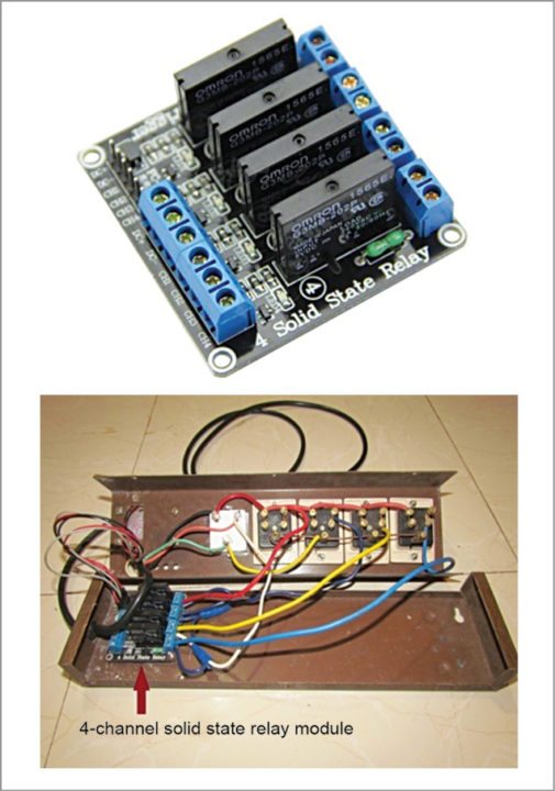
Each bulb holder and push-button switch is mounted on a suitable box, with separate pair of wires for the bulb holder and the switch. GPIO board numbering is used throughout the project. Push-button switches’ wires are connected to GPIO pins 11, 13, 15, 16 and common to ground pin 9 of Raspberry Pi as shown in Fig. 1. A 5V, 4-channel solid-state relay module (refer Fig. 2), purchased from ebay.in, is connected to Raspberry Pi GPIO pins 18, 19, 21 and 23.
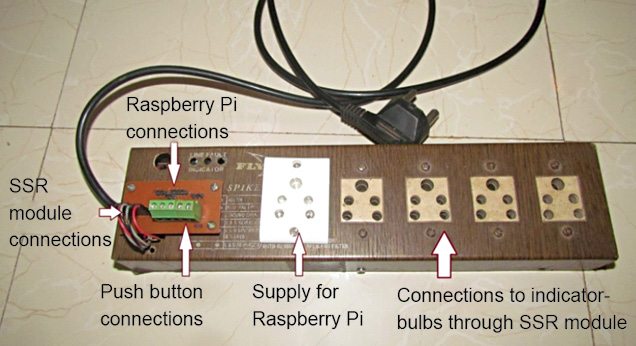
A 5V supply is given to relay module from Raspberry Pi. Coloured indicator bulbs (Bulb 1 through Bulb 4) are connected to the output of the relay board with 230V supply as shown in Fig. 1. System’s various connecting points are shown in Fig. 3.
Run the rasquiz.py Python script on the terminal by giving the command:
$ sudo python rasquiz.py
The program executes from main subroutine. It prompts for user inputs like names of the teams and allowable time (in seconds) to respond to a question. Then it clears the screen and prompts you to continue or to stop. To continue the game, type 1 followed by pressing ‘Enter’ key. Raspberry Pi initialises the push-button switches’ pins as input and clears the solid-state relay pins to switch off the indicators.
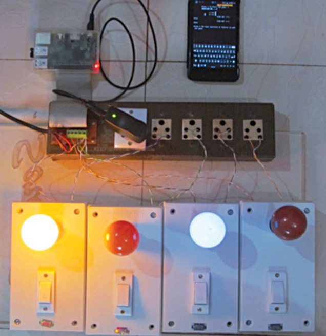
As soon as contestants press their switches, names of the respective teams with their rank numbers get displayed on LCD screen, along with glowing of respective indicator bulbs. If no contestant presses the switch within specified time, all the switches’ pins get latched, so no more inputs will get registered and ‘Time Up’ message is displayed on screen.
By typing Ctrl+C keys at any time, the host or operator can stop the quiz without restarting the whole system or waiting till time up. When prompted, enter 1 to continue or 0 to quit the game.
Download source code: click here
Check more such tested Raspberry Pi projects with source codes
Nitin Kisan Palte is a B.E. (instrumentation) and an electronics hobbyist, currently working as instrument mechanic in College of Agricultural Engineering and Technology, Dr Balasaheb Sawant Konkan Krishi Vidyapeeth, Dapoli.
This article was first published on 5 September 2016 and was updated on 9 April 2020.

Wouldn’t an Arduino or other micro-controller work better than an rPi? The Linux system of the rPi could be doing other work when the first person presses the button, thus your python script will miss the actual first button press, and could then perhaps read the next persons press instead!