


 You may be wondering about this article on a crystal radio in an era of digital broadcasting and digital audio. Crystal radios were quite popular and played an important role in communication from 1920s to 1940s. The number of people using crystal radio substantially reduced after transistor radios came into the market in 1960s.
Even though the crystal radio is a hundred years old, it is still living as a hobby in several countries where medium wave (MW) and short wave (SW) amplitude modulated (AM) transmission are available on air.
Several crystal radio forums and groups are still active and their highly advanced crystal radios can receive radio stations several hundred kilometres away. Search on Wikipedia, You Tube, and Google provides a lot of information on crystal radios and it is a good place to learn more about it.

Crystal radio is the pioneer of widely used radio receivers, though it is almost forgotten now in most countries including India. Construction of crystal radio was a thrilling and fascinating hobby of all radio hobbyists of those days (including two of the authors who were teenagers in 1960s). A crystal radio needs no battery or power and works on the microvolts of radio signals received from its antenna.
India has more than 300 medium wave radio stations located in major cities and towns. The presence of these radio stations offers an opportunity to construct crystal radios for electronics hobbyists, including school and college students. Our neighbouring countries like Sri Lanka, Malaysia, and Singapore have already shut down all amplitude modulated (AM) medium wave stations and switched to frequency modulated (FM) transmission.
So, the present-day electronics students, teachers, and hobbyists in India are really lucky as they can still enjoy amazing power of the tiny crystal radio since plenty of AM stations are available to tune in to.
But how many present-day electronics hobbyists, school students, and engineering students are even aware of this excellent piece of electronics is still a question. Hence, this article is intended to reintroduce this simple radio and to revive interest in crystal radio among school students, and several thousands of engineering students passing out from thousands of engineering colleges/Universities across India. The circuits provided here are not our own but a rediscovery of the knowledge present during the 1930s.
A crystal radio needs no battery or power and works on the microvolts of radio signals received from its antenna. It works non-stop (24×7) as long as the transmission is on air.
The construction of crystal radio is remarkably simple with just four components required to make it. It needs an antenna, a good earth connection, a germanium diode, and a high-impedance headphone.
You will be fascinated by the working of crystal radio provided you live in or near a city where a MW wave radio station is in operation. However, those who live far away from a MW station can also receive the radio signal with the help of a tall and long aerial (antenna) and good earth connection. Although long wave (LW) and short wave (SW) crystal radios were also constructed by several people, this article focuses on crystal radio that receives MW amplitude modulated transmission as we have a lot of MW stations in India to receive.
Before constructing the crystal radio, please understand that this crystal radio does not have an amplification circuit. So, the sound output totally relies on how effective the antenna and earth are, besides the power of your local radio station and the distance between your radio and the transmitting tower. A minimum of 18-metre single-core or multistrand hookup copper wire (14/36), or 20SWG enameled copper wire antenna, erected in open terrace will work well.
It is better to know about the transmitting power of the nearby radio station. In India, some cities like Dibrugarh (Assam), Jammu, Srinagar, Nagpur, Imphal, Jalandhar, Lucknow have 300kW high-power transmitters and other cities like Ahmedabad, Alleppey, Ajmer, Bengaluru, Mumbai, Kolkata, Chennai, Delhi, Dharwad, Hyderabad, Indore, Jabalpur, Siliguri have 200kW transmitters. Those who live in and around these cities will get good reception from local stations with the crystal radio.
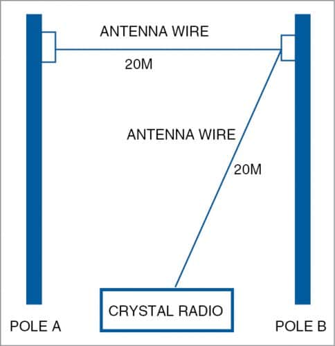
Further, there are 100kW, 50 kW, and 20kW MW transmitters in operation in various cities and towns. Those who live near low-power stations (20kW) can use an amplifier as described in this article. Visit www.allindiaradio.gov.in for the list of all radio stations with their power in kilowatts. Those who live near high-power radio stations (300kW or 200kW) can have an antenna of about 20 metres (see Fig. 1). For low-power areas, one should have a longer antenna that can go up to 36 metres (120 feet). If space is a problem, the antenna wire can be arranged in L or U shape around the house at the maximum possible height (say, 6 to 9 metres), ensuring that the wire does not touch a wall.
Components required for a crystal radio are:
1. A good aerial/antenna made of 18 to 36 metres (60 to 120 feet) long enameled copper wire (18 or 20 SWG), or insulated copper wire (hook-up wire: 14/36 ) at a height of 6 to 9 metres (20 to 30 feet).
2. A good earth connected to a metallic water pipe through a tap. In recent days, PVC pipes are used for water lines instead of metal pipes, so double-check the earth connection if your crystal radio does not work. In that case the earth point of an electrical wall socket can be used with due care. (WARNING. Please consult an experienced electrical engineer before using earth connection from a wall socket as improper connection can be dangerous and even fatal!)
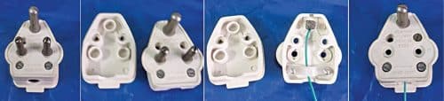
To use an electrical wall socket for the earth, take a 3-pin plug and open it by unscrewing the retaining screws. Remove the two small pins meant for ‘Line’ and ‘Neutral’ and discard them. Connect one or two metres of insulated copper wire to the bigger and thick pin meant for ‘Earth’ connection. Now close the plug using the screws. The other end of the wire is to be connected to the earth point of the crystal radio, and the modified plug needs to be inserted into the wall socket (see the photos of the modified plug in Fig. 2).
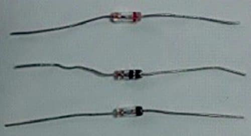
3. A 1N34A or equivalent germanium diode or Schottky diode 1N5817/1N5818 (which would require much longer antenna). Most diodes sold as germanium diode 1N34A (refer Fig. 3) in electronics markets do not have marking on them, and many of them are not actually 1N34A and so do not work in a crystal radio. The diode having a forward voltage (Vf) of less than 300mV works with crystal radios and any diode having its Vf more than 300mV will not work. Vf of 225mV to 250mV is the best choice. You can check the Vf of a diode using a digital multimeter that has Diode Check facility.
Set the selector switch of the multimeter to the Diode Test symbol. Connect black probe of the multimeter to cathode terminal of the diode. The cathode terminal is on the side with a black or red or any other coloured band. Connect the red probe to the other terminal (anode). The reading on the meter will show the forward voltage. If the forward voltage is less than 300mV, you can use this diode for your crystal radio.
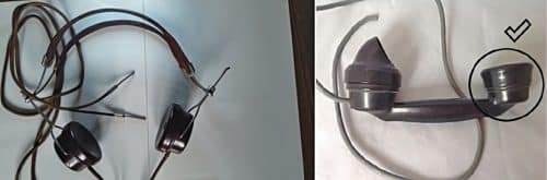
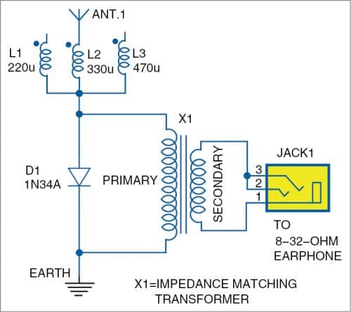
4. A good high-impedance headphone having 2,000 to 4,000 ohms DC resistance, or landline telephone earphone having 150 to 300 ohms DC resistance (refer Fig. 4), or an earphone used for MP3 players or cellphones having 16 to 32 ohms resistance with an impedance-matching transformer (refer Figs 5 and 6). Nowadays, it is difficult to obtain high-impedance headphones. If you are lucky, you may get it in junk market in a big city.
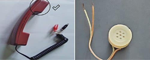
Most of them are usually condemned as military surplus but still work. Most Ham radio operators have such high-impedance headphones. If high-impedance headphones are not available, you can use the earphones of an old type of landline telephone receiver (dial type), or the handset of the latest pushbutton landline telephone.
For using the telephone handset for crystal radio, cut the wire that connects the handset with the main unit. You will see four wires of different colours, of which two are connected to earphone and two to microphone. Ignore the microphone wires. Check the DC resistance across the two wires of the earphone/headphone using a multimeter. For best matching, it should be 300 ohms or above for use in crystal radios. In our experiment, earphone from pushbutton telephone handset with 150 ohms DC resistance also worked, but with less volume compared to high-impedance earphones. Connect a pair of miniature crocodile clips to the earphone wires, which will facilitate easy connection with the crystal radio.
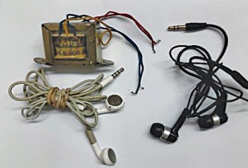
If you are not able to get a high-impedance headphone or landline telephone’s handset, you can use currently available low-impedance earphone of an MP3 player or cellphone (16 to 32 ohms impedance) along with an impedance matching transformer. The commonly available step-down transformer of 220V primary to 9V or 12V, 500mA secondary, which is used for low-voltage power supplies, can be used as an impedance-matching transformer.
Everyone has a cellphone’s earphone, which is also freely available in the market. Select an earphone with a sensitivity of 100 to 110dB/mW. Try different brands of earphones for the best results. Connect the primary winding of the matching transformer, as in the circuit, and connect the earphone to the secondary of the transformer. You will be able to listen to audio of the nearby MW station.
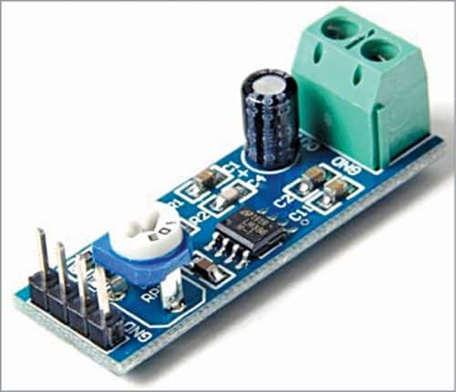
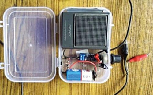
If you are getting a low volume in your headphone or earphone, you can always use a matching amplifier and connect it in the place of the headphone. A mini amplifier based on LM386 IC is the best match for the crystal radios. It is low in cost and works off 3V to 9V battery. You can get a fully assembled LM386 amplifier module (refer Fig. 7) from an electronics market or assemble it yourself. Authors’ prototype is shown in Fig. 8.
Circuit 1
This circuit (refer Fig. 9) uses just two parts, one germanium diode and a pair or single high-impedance headphone, apart from an antenna and earth, as described earlier. The germanium diode is connected across the headphone terminals. The cathode of the diode is connected to the long wire antenna and anode to a good earth (metallic water pipe or the electrical socket). The polarity of the diode is not critical, and you can connect the diode in any direction as we use only half of the rectified signal.
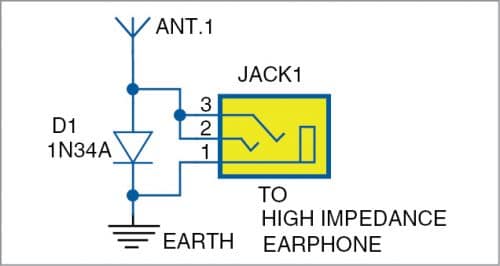
Enjoy listening to the local station with high or low volume depending upon the length and height of the antenna, power of your local radio station, and how far away you are located from the transmitter. If you do not get sufficient volume with this circuit, you can try the second circuit with the addition of moulded inductors.
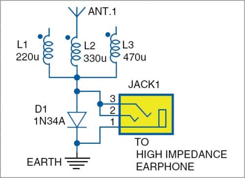
Circuit 2
This circuit (refer Fig. 10) is similar to the first circuit, but a moulded inductor of 220, 330, or 470 micro-Henry is added in series between the antenna and the diode. Select any one of the inductors that gives better volume. As the inductor helps to select the MW band, a slight increase in audio output is observed.
Circuit 3
In case you are not able to get the high-impedance headphone or pushbutton phone earphone, you can use your cellphone’s or MP3 player’s earphone having a low impedance of 16 to 32 ohms along with the impedance-matching transformer described earlier. As shown in Fig. 11, connect primary of the transformer to the terminals of the diode and secondary to the earphone. For best results, select earphone with a sensitivity of 100 to 110dB/mW. You will be able to listen to the radio with the earphones.

Circuit 4 without antenna and earth
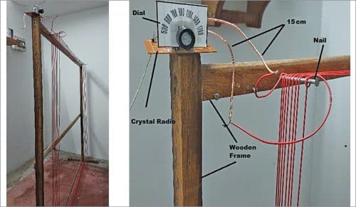
You can make a crystal radio work even without an outdoor antenna and earth as shown in Fig. 14. This is an interesting circuit for those who do not have adequate space for erecting a long antenna, or do not wish to use an antenna and earth for some reason and still receive the stations.
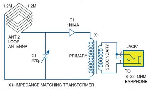
The antenna used in this circuit is called ‘Loop Antenna.’ It is made of eight turns of a multi-strand hook-up wire (14/36) on a 120cm×120cm (4×4 feet) on a wooden frame with legs to make it stand on the floor. You can also use smaller frames but bigger the size, better the signal output. The photo in Fig. 12 shows the crystal radio using the loop antenna made by the authors.
Components required:
- Wooden frame of about 120cm x 120cm with legs
- Multistrand hookup wire (14/36) – 40 metres
- Variable capacitor rated 270pF (dual gang) – 1
- 1N34A diode – 1, or any germanium diode with Vf less than 300mV
- Perforated PC board of 7.5cm× 3.8cm (3”×1.5”) – 1
Make a wooden frame of about 120cm×120cm with legs so that it can stand on the floor. Nail the four corners of the frame with 10cm iron nails or screws. Start running the hook-up wire with a knot from the left top nail, leaving about 15 cms of wire at the start. Make eight turns clockwise from left top, right top, right bottom, left bottom, and back to left top nail, and leave an extra 15cm of wire for making connections with PC board circuit. Maintain a small gap of 4 to 5mm between each turn.
Connect the loop, variable capacitor, and diode as in Circuit 4. The terminals to be connected to the headphone may be connected with miniature crocodile clips for easy interchange between high-impedance headphones or the primary of the matching transformer. Tune the variable capacitor either clockwise or anticlockwise, slowly, and you will hear the audio when the frequency of the local station matches with the capacitance. The loop antenna is very directional and hence it should be rotated slowly and oriented towards the direction of maximum volume.
The advantage of using a loop antenna in crystal radio is that it does not require an external antenna or earth. The radio signal picked up by the loop antenna is slightly lower than that from an external antenna.
Troubleshooting
Crystal radios use only an antenna to receive the radio signal and a diode to rectify/convert the radio signal to audio signal to be heard using a headphone. It is entirely passive and has no active components like transistors or ICs, and no battery or electricity is used.
Hence the volume obtained in the headphone/earphone is relatively low. To receive a radio station properly, check the following points:
- You have a long wire antenna of a minimum of 18 metres at a height of 6 to 9 metres. If you live in a city where the power of the radio station is 200 or 300 kilowatts, 18 metres long antenna gives the best results. If you live in low-power area, make the antenna longer.
- You have a good earth connection.
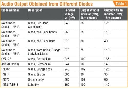
- A diode is the heart of the crystal radio. Confirm that you have chosen the right type of germanium diode. Variations are found in the diodes available in the market, as most of the diodes sold as 1N34A have no marking on them and you cannot be sure whether you are using a correct diode. The failure to receive local radio stations (despite long antenna and good earth) is mostly due to the diode. One has to check the forward voltage as mentioned earlier while using the diode and try several diodes for getting good results. We used Schottky diode 1N5817/5818 instead of germanium diode and successfully received radio programmes with an external antenna longer than 18 metres.
Table 1 shows the audio output obtained from different diodes. The output of the diode is connected to a digital multimeter (Mastech 830L) in the place of headphone and measured as DC millivolts. This data is pertaining to Chennai-A radio station (720kHz) with a power of 200 kilowatts. The crystal radio is located about 45 kilometres away from the transmitter. Antenna length is 18 metres of 20SWG enameled copper wire. The audio output obtained from different diodes may vary based on the height and length of the external antenna and also depending on the distance from the transmitter.
Caution. There is a high chance of electrical shock if electrical earth point is not identified and handled properly. Novice experimenters are advised to consult an experienced electrical engineer before using an earth connection from wall socket.
Dr N. Mohan retired as assistant professor and in-charge of instrumentation lab, in the dept. of botany, University of Madras. He is a radio and electronics hobbyist for more than 40 years.
Prof. S. Ananthi recently retired as a professor and head of the department of Network Systems and Information Technology, University of Madras.
K. Padmanabhan retired as a professor at A.C. Tech and University of Madras.
Thanks for the article. It reminded me of my school days. I managed to get the earpiece from a telephone operator. Connecting the crystal diode across the terminals and with earth and roof top arial I could listen to AIR, Guwahati.
The article makes me nostalgic.
I was bitten by the ‘Crystal Radio’ bug over 50 years ago!
Hi,
I had used OA70 diod with an ear piece of telephone operator working at mannual telephone exchange during 1970, one end of ear piece used to put in nagative point of electric pluf & other end used to just touch with finger! It was working good but within 5km area of radio station.
Anyone can advise about OA70, please?
Thanks
Hi, we have added your query to our forum page, you can follow this discussion here: https://www.electronicsforu.com/forums/topic/anyone-can-advise-about-oa70-diode