


Summary:
- Automatic solar garden lights provide nighttime illumination without requiring grid power or complex wiring.
- A small solar panel charges a rechargeable Ni-Cd battery during the day and automatically switches the LED off.
- At night, the stored battery energy powers a bright white LED through a solar lamp controller IC.
- The solar cell also acts as a light sensor, eliminating the need for an LDR or phototransistor for dusk-to-dawn operation.
- The CL0116 controller IC integrates battery charging, LED driving, and boost conversion functions with over 90% efficiency.
- A single rechargeable battery (typically 600mAh–1000mAh) can power the LED for more than five hours, depending on capacity.
Many homes come with backyard gardens or open spaces, and adding a garden light can make these areas usable at night. But traditional lighting setups often come with wiring hassles, which can get in the way of movement and disturb the plants.
A better solution? Automatic solar garden lights. They offer bright illumination without the need for complex wiring or a connection to the grid. Plus, they help lower your electricity bill while keeping your garden eco-friendly and hassle-free.

Solar Light Circuit
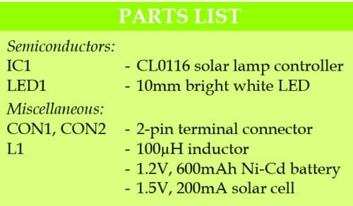
Circuit diagram of the solar garden light is shown in Fig. 1. It is built around a solar lamp controller IC CL0116 (IC1), a miniature solar cell, a bright white LED (LED1) and a few other components.
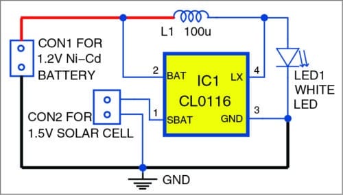
This circuit requires only a single Ni-Cd rechargeable battery to light up the white LED for more than five hours, depending on the ampere-hour (Ah) capacity of the battery.
When sunlight falls on the solar cell during the day, the solar cell charges the rechargeable battery and turns LED1 off. When no light falls on the solar cell during nighttime, the IC draws power from the battery and provides a constant current to light up LED1. Since the solar cell acts as a light sensor, there is no need for a photo-transistor or light-dependent resistor for automatic switching of the LED in the dark.
Lamp controller
IC CL0116 lamp controller is an application-specific integrated circuit (ASIC) in which solar charging and LED driving sections are integrated on the chip. It requires only an external inductor to construct a boost power supply with over 90 per cent efficiency. It offers the advantages of low power dissipation, low minimum operating voltage and automatic dusk-to-dawn switching.
IC CL0116 is available in a TO-94 package, and its overall circuit can be enclosed in a matchbox. There is no need of an external current-limiting resistor for the LED because the LED driver circuit is integrated in the controller IC.
The IC operates off 0.8V to 3.0V. The voltage on the SBAT pin should not go beyond 3.0V. For better protection, connect a 2.7V zener diode between SBAT pin and ground to maintain 2.7V if the solar cell voltage goes above 2.7V.
Solar cell
A 1.5V, 100mA solar cell is sufficient to charge the battery and light the LED. It can be mono-crystalline or polycrystalline. The nominal current of the solar cell should not be more than 800mA. For better performance, use a solar cell with a nominal current below 400mA.
Solar Light PCB Design
A PCB layout for the garden solar light is shown in Fig. 2, and its component layout in Fig. 3.

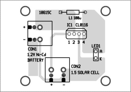
Download PCB and component layout PDFs: click here
Assemble the circuit, together with the LED, on the PCB. Use a wire length of not more than 5cm to connect LED1 to the IC. A readymade inductor can be used for the circuit. For better performance and efficiency, use a low equivalent series resistance (ESR) value of inductor for the circuit. The circuit can fit in an old torchlight enclosure with appropriate modifications.
Fix the connector CON1 and LED1 on the front, and CON2 at the top of the enclosure to connect the solar cell.
Conclusion
Solar lights offer an efficient, eco-friendly solution for illuminating outdoor spaces. By integrating components like solar cells, lamps, and controllers, these systems provide reliable lighting. They not only reduce electricity costs but also promote sustainability, making them an ideal choice for modern gardens. With easy installation and minimal maintenance, solar lights are a practical, long-term investment for anyone looking to enhance their outdoor living areas.
EFY notes
1. Battery capacity of 600mAh to 1000mAh is large enough for this circuit.
2. In place of CL0116, you can use QX5252F, ANA608 or YX8018.
Frequently Asked Questions
Q 1: How does an automatic solar garden light work?
An automatic solar garden light uses a solar panel to charge a rechargeable battery during the day. At night, a controller IC detects the absence of sunlight and powers an LED using the stored energy, providing automatic dusk-to-dawn lighting.
Q 2: Does a solar garden light require external wiring?
No. Solar garden lights operate independently using a solar panel and rechargeable battery, eliminating the need for external wiring or a connection to the electrical grid.
Q 3: What battery is used in this solar garden light circuit?
The circuit is designed to work with a single rechargeable Ni-Cd battery. A battery capacity between 600mAh and 1000mAh is generally sufficient for reliable operation.
Q 4: How long can the solar garden light stay illuminated?
Depending on the battery capacity and charging conditions, the solar garden light can power the LED for more than five hours after sunset.
Q 5: What is the role of the CL0116 controller IC?
The CL0116 integrates solar battery charging, LED driving, automatic day-night switching, and boost conversion functions into a single chip, simplifying the circuit design and improving efficiency.
Q 6: Can other controller ICs be used instead of CL0116?
Yes. Compatible alternatives include QX5252F, ANA608, and YX8018, which offer similar functionality for solar-powered LED lighting applications.
Q 7: Does the circuit need an LDR or phototransistor for light detection?
No. The solar panel itself acts as a light sensor, allowing the circuit to automatically switch the LED on at night and off during the day without additional sensing components.
Q 8: What type of solar panel is suitable for this project?
A 1.5V, 100mA solar panel is sufficient for charging the battery and powering the LED. Both monocrystalline and polycrystalline solar cells can be used.
Q 9: What are the benefits of solar garden lights?
Solar garden lights reduce electricity consumption, eliminate wiring costs, require minimal maintenance, and provide an environmentally friendly solution for outdoor lighting.
Q 10: Can the solar garden light circuit be installed in a compact enclosure?
Yes. The circuit uses very few components and can be assembled in a small enclosure such as a modified torchlight housing, making it suitable for compact outdoor installations.
Check 10 solar electronics projects you can build at home.
This article was first published on 21 November 2017 and updated on 11 June 2026.

How to make enable that ic cl0116 auto switch the led when light falls on the solar cell. I have majedar this project but it is not working properly.
what is rets of this cicuit.
I am in Bangalore I am trying to get the IC Cl0116 or Qx5252F or ANA 608 not able to find .request help to fond the outlet
Found on Ebay
Where to get these ICs CL 0116 or ANA 608 or QX 5225F or YX 5225F in india. trying to find request help
You can buy the IC QX5252F from the online store https://rarecomponents.com/store/1580.
I built this circuit and it works ,except for one problem. The LED blinks. What could be causing this?
Thanks.
Hello.
It could be the LED is to close to the solar panel and is tripping the day night function.
The LED light should not shine on the solar panel.
Thanks John.
Please check proper connections between the IC, inductor and LED
The YX8018 is different from the other alternatives given. Its solar cell input has one side connected to Bat+ not Bat-.
For my Solar Garden light I took the NiCd battery out of an old razor. I used a four volt fifty mili-amp solar panel. And I used a small one watt light emitting diode. I used a cheap used ham salad bowl for the enclosure. Though I should have put another inductor on it. Two large inductors in parallel reduce inductance. I poked a hole though the lid and ran the wires though of the solar panel. I attached the panel with a hot hot glue gun. Then I used more glue to attach the large battery to the center of the lid by the wires. I glued the circuit on top of the cell with hot glue as well. I wired everything up. Glued the wires down and it worked good. The battery was a 1500ma hour at 1.2v. And the circuit was form a dollar light. The panel was bought from a science surplus mag years ago. But you can find at least 2v at about 400ma on amazon or other sites.
Hi,
I would like to use two AA batteries(2.4V), can you tell me what part ratings need to be adjusted to the solar panel, and charging circuit.
Thanks for your time
Hello, I have a set of solar garden lights for some reason only the first 10 lights are working now. Could you please let me know why.
Thanks
Shirl Cole.
I have a solar garden light that has three wires and it does not work. I was wondering how to fix it.
Dear Dames,
You are talking for another circuit having three wire.
Unable to reply without referring your circuit.
Regards