


 Drones, autonomous cars, and robots are being a massive hit in recent times. Real-time tracking is much needed for all these devices. In the case of autonomous cars, trajectory tracking helps to detect slopes, curves and bends on the road.
This data lets the car move in the right direction and also helps in further analysis for new algorithms to be set up.
This Trajectory Tracking DIY project is a simple system that can receive and store real-time trajectory data. Either this data can be sent from the GPS to obtain the trajectory of the device over Bluetooth, or can be recorded and later used to view the trajectory.
Note that sending and recording the data can also be done simultaneously.
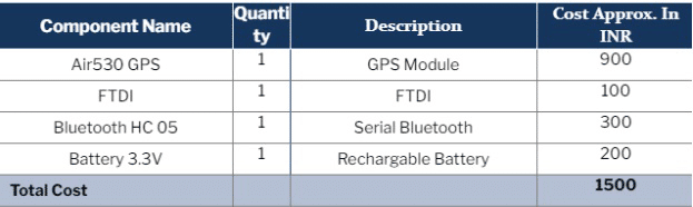
The components listed in the bill of materials table are needed for this project.
Bill of Material
Software Required
Verios software has to be installed as it helps connect the GPS module and the data collected. It also helps in recording the data received. The SIM COM software also has to be downloaded to check the GPS signal and other related data.
To get the GPS data and view it in a real time-map, U-BLOX (U_centre) must be downloaded. This software helps in connecting the GPS and gives a live position while recording the data and obtaining the trajectory.
Circuit Connection
The AIR530 GPS has to be connected to a PC. This module is finger-sized and can run a mini CR3.3 V battery. This is connected to an FTDI module in the case of autonomous cars. For a drone, it is connected wirelessly with Bluetooth HC05.
The GPS pin is connected to the FTDI/Bluetooth module as seen in the circuit diagram. Both FTDI and Bluetooth modules are basically serial converters that use the USART pin.
This means Vcc is the power pin; GND and USART pins are Rx and Tx respectively. The pins should be connected as per the circuit diagram.
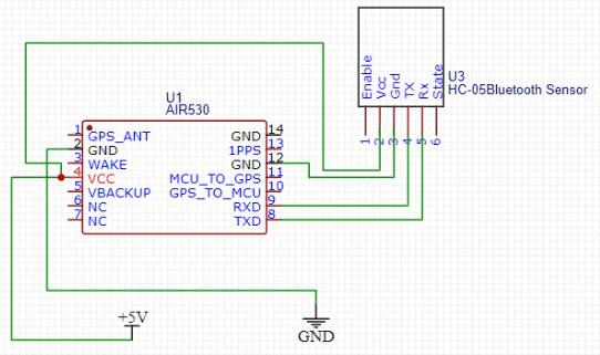
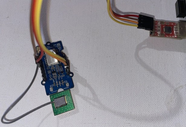
Based on the device being used, the FTDI or Bluetooth is connected. Here the FTDI is being used and is thus connected via the USB port to the laptop.
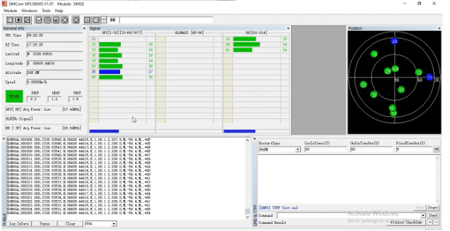
Note the name of the COM port that can be seen on the ‘device manager’ from ‘PC settings’ under the COM port number. Next, open the SIM COM software and then select the COM port and baud rate.
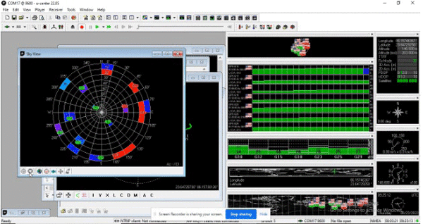
The default baud rate of our GPS module is 9600. After connecting it to the GPS, the Serial COM starts displaying the data. Wait for a few moments till the GPS is properly fixed. Once the GPS is connected with the satellite, the ‘fixed’ button turns GREEN with the latitude and longitude displayed.
If the ‘fix’ is in 3D, the altitude can also be seen.
The GPS can now show the data of a location. The next step is to map the trajectory from the recorded data to view the path taken. This can be viewed from the U-Blox software that has been installed.
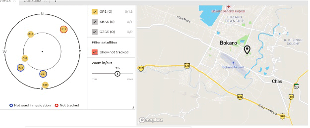
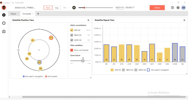
Connect the U-centre with the GPS device via the right serial port and baud rate. You will now be able to see the altitude, longitude, latitude, azimuthal angle, speed, etc. as long as your device is moving.
The speed can also be seen along with the nearby satellite to which the GPS is connected.
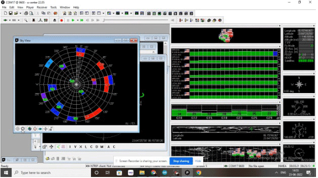
To record the data, the red record icon must be clicked.
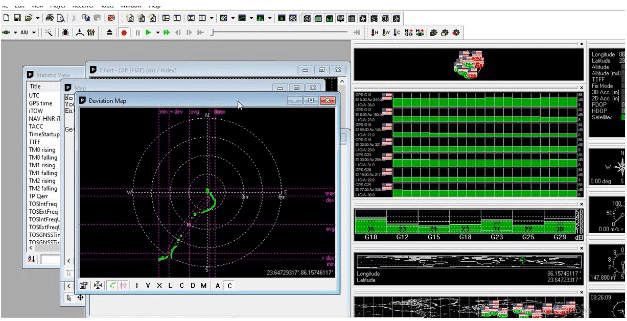

Once the GPS data is recorded, it is saved in a .ubx format. On another browser, open the data and convert it to view the trajectory of the device. You can convert it using gpsvisualizer.
Once the data has been converted, it can be viewed in .PNG or .KML format. To view the path on Google Earth, .KML format can be used. (as seen in figure 16).
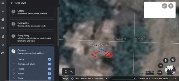
This is how you can get real-time GPS trajectory data.
Is there any other option to receive real-time trajectory-tracking data? If you know the simpler and easy way…let everyone know in the comments below.
Here are some interesting GPS Tracking DIY Projects:
One more thing…
This Article was Updated on 28-10-2022.
Nice article on new topic
Thank you for your feedback