


 Sometimes we do not notice that the battery has drained out and as a result the connected equipment does not work properly. By connecting this simple 24V/12V battery voltage level indicator circuit across the battery, you can check its voltage level any time.
The circuit can be used to check 24V and 12V batteries both. The battery level is indicated by the ten LEDs. Each glowing LED indicates 10% of battery voltage level. So, when LED1 through LED5 are glowing, or just LED5 is glowing, it means the battery is around 50% charged. The circuit can help in checking the batteries for a car, inverter, solar system, etc.
Video Tutorial:

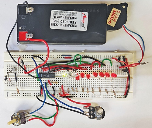
The author’s circuit rigged on a breadboard is shown in Fig. 1 while the circuit’s block diagram is shown in Fig. 2.
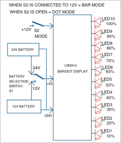
As shown in the block diagram, when LED1 alone glows it means the battery level is only 10%. With LED2 also glowing it means the battery level is 20%, and so on. When all the LEDs (LED1 through LED10) are glowing, it means the battery level is 100% and it is fit for use.
Switch S1 is used to monitor either 24V or 12V battery. Switch S2 helps select dot mode or bar mode display. In dot mode only the last LED representing the voltage glows while in bar made all the LEDs up to that LED glow. The choice is yours.
Circuit and Working
Circuit diagram of the battery voltage level indicator is shown in Fig. 3. It is built around IC LM3914 dot/bar driver IC1, 1N4007 diodes D1 and D2, ten 5mm LEDs (LED1 through LED10), 12.1V Zener diode (ZD1), BC547 transistor T1, BC557 transistor T2, presets VR1 and VR2, and piezo buzzer PZ1.
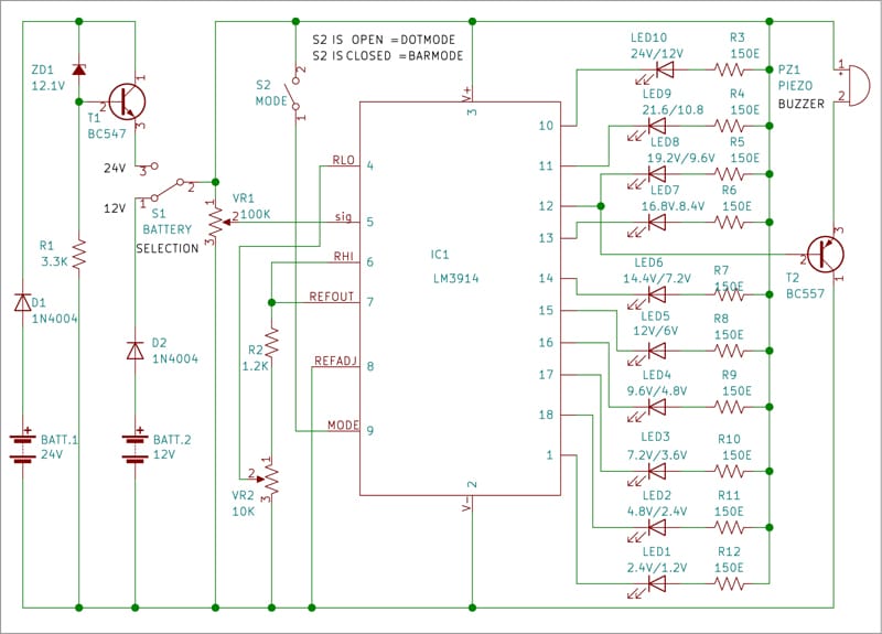
The LED display comprising LED1 through LED10 shows voltage level of the 24V or 12V battery selected. This display can be set in dot mode or bar mode. For showing the voltage level in bar mode, connect pin 9 of the IC to positive terminal of the battery using switch S2. For showing the voltage level in dot mode, simply open switch S2.
Download PCB and Component Layout PDFs: click here
The 12.1V Zener diode ZD1 is used along with BC547 transistor T1 to reduce the 24V battery voltage to 12V. Pin 3 of IC1 is connected to positive side of 12V to operate the circuit while its pin 2 is connected to ground.
To check voltage level of the battery, use two crocodile clips with about 30cm long wires soldered to each. One of the clips could be red with red wire soldered to it and the other black with black wire soldered to it. Connect red clip to positive terminal of the battery under test and black clip to its negative terminal. Flip switch S1 for checking a 24V battery’s status. Position of switch S2 will depend on whether you want a dot display or a bar display.
Use presets VR1 and VR2 to calibrate the circuit. And you may use a 30V variable power supply instead of the 24V battery for calibration. Connect 12V from the variable power supply in place of 24V battery in the circuit. Adjust preset VR1 such that LED1 just starts glowing. Now increase the input DC voltage slowly to 24V and observe the LED’s glowing status. The first LED (LED1) will start glowing at 2.4V and the second (LED2) at 4.8V, and so on. The last LED (LED10) will glow at 24V.
After this calibration the circuit is ready to use. If you want to check the level of a 24V battery, connect it to the circuit using the crocodile clips and flip switch S1 towards 24V position.
To see the voltage level in dot mode, keep switch S2 open. If, say, LED9 glows, it means voltage level of the battery is around 90% of 24V, that is, around 21.6V. If LED10 glows, it means the battery is fully charged.
To see the battery voltage level in bar mode, flip switch S1 towards 24V position and turn switch S2 on. If, say, LED1 through LED9 start glowing, it means voltage level of the battery is around 90% of 24V, that is, around 21.6V. If all the ten LEDs (LED1 through LED10) glow, it means voltage level of the battery is full 24V.
The buzzer in circuit sounds when the battery’s voltage level falls to 80% to indicate that the battery needs to be charged. The base of transistor T2 connected to pin12 of IC1 drives the piezo buzzer.
Construction and Testing
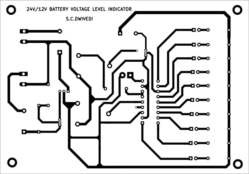
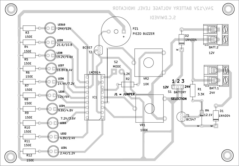
An actual-size, single-side PCB for the 24V/12V battery status indicator is shown in Fig. 3 and its component layout in Fig. 4. After assembling the circuit on PCB, enclose it in a suitable plastic box. Switches S1 through S2 may be fixed on back side of the cabinet. The assembled PCB may be fixed inside the box’s front side in such a way that LED1 through LED10 are clearly visible.
BONUS: You can watch the VIDEO of the tutorial for this DIY project click on the link.
S.C. Dwivedi is an electronics enthusiast and circuit designer at EFY
