


This project deals with the design and development of a portable wind turbine unit, capable of generating electricity from the kinetic energy in the wind. The circuit requires a DC motor, fan blades or propeller, DC-DC boost converter and wind energy to produce a 5V DC output.
Wind-power generation is a fairly simple process that uses an ordinary miniature DC motor to make a very simple wind turbine generator. A miniature DC motor, like RF-300FA-12350, is easily available in the market but can also be taken out from an old CD/DVD drive/player (refer Fig. 1).
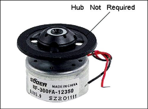

A small propeller, or fan blades, can be mounted directly onto the motor shaft. Note that the electricity generated by the motor is DC, and hence no AC-DC conversion circuitry is required apart from a polarity guard diode. In fact, the polarity guard diode is also not required since the propeller rotates in only one direction (counter-clockwise) in this model, due to the unique design structure of the plastic wind turbine blades/propeller.

Compact and light-weight plastic fan blades/propellers are available. A generic three-leg plastic propeller (shown in Fig. 2) is used in this project.
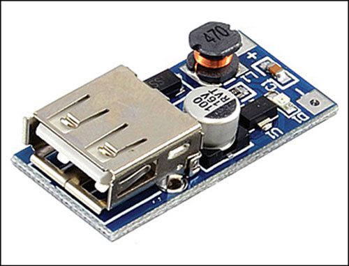
Since a miniature DC motor is used as the rotary engine, only a small amount of DC supply (three to five volts maximum) is available at the output. So, a DC-DC boost converter circuit is required to provide a stable 5V DC output. Any home-made/ready-made DC-DC boost converter circuit can be used for this, however a ready-made DC-DC boost converter module based on pulse frequency modulation (PFM) technique with a standard USB output port, as shown in Fig. 3, is preferred.
If an input voltage of 0.9V to 5V DC is available, this module gives a stable 5V DC output through its USB connector, with conversion efficiency up to 96 percent.
Circuit and working
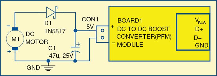
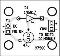
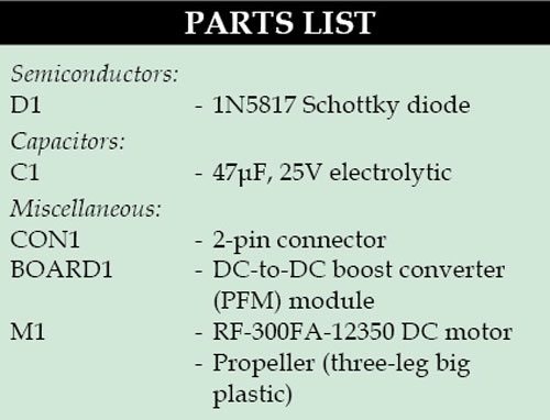 As shown in Fig. 4, the circuit is built around a DC motor, Schottky diode 1N5817 and DC-DC boost converter module. Working of this small DC-DC boost converter module is based on pulse frequency modulation (PFM) technique.
A PFM converter is an alternative DC-DC power converter architecture that uses a variable frequency clock to drive power switches and transfer energy from input to output. Because the drive signal’s frequency is directly controlled to regulate the output voltage, this architecture is referred to as PFM. DC-DC converter with constant-on-time or constant-off-time control is a typical example of this architecture.
In the circuit diagram, the negative terminal (black wire) of DC motor M1 is treated as the positive output terminal, connected to PFM module (board 1) through polarity guard diode 1N5817 (D1), because the motor rotation is in counter-clockwise direction. The PFM module is connected across buffer capacitor (C1) to get a USB-standard 5V DC output through its USB (A-type) connector.
Portable wind turbine construction
An actual-size, single-side PCB for deriving 5V from portable wind turbine is shown in Fig. 5 and its component layout in Fig. 6.
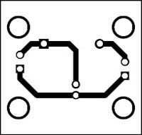
Download PCB and Component Layout PDFs: Click here
Good air flow is essential for the proper working of the circuit. You can use an ordinary electric fan (or table fan) or an electric air blower as the wind-energy source for testing purpose. Ensure that air flow from the wind source directly falls at the front of the propeller. The propeller should rotate at a fast speed (in counter-clockwise direction) to get higher output.
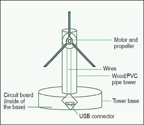
You need rigid mounting for the wind turbine system. For this, you can fix the motor on a suitable-sized PVC/metal pipe and attach it to a base support as shown in Fig. 7. The base support can be a small-diameter disc made of wood or metal. Connect the PFM module to the circuit at CON1, enclose these in a suitable cabinet and place inside the base in such a way that you can access the USB port conveniently.
Next, route the wires from the DC motor through the pipe to the base and connect the wires to the circuit at M1. Face the propeller towards a wind source. Now, you are ready to get 5V DC output from the USB connector. This output can also be used for charging your mobile phone.
Caution! Rotating blades are sharp and can cause severe injury if not handled properly.
T.K. Hareendran is an electronics hobbyist, freelance technical writer and circuit designer

What is the output current?
I think you can hardly glow an LED with this circuit.
in this entire experiment what is work will done by DC DC boost converter
it works.. for me!!
but it can charge only keypad phones..
not android.