


Using radio frequency identification (RFID) technology, this project aims to create an intelligent traffic system. It is developed and operated in such a way that fines are tracked independently. RFID technology, passive tags, a processing unit (computer), and a communication system were all utilized with low-cost equipment. The first level is represented by data collection via RFID, which scans any identifiable tag connected to cars. Following that, data is sent to the server over the internet network connection method.Modern technology is always improving in order to make people’s daily tasks easier. One of the major issues facing developing cities is traffic management, which is exacerbated by increasing population density and vehicle numbers without expanding city highways. This study demonstrates that developing a traffic management system using the Internet of Things (IOT) is doable and inexpensive.
Introduction
In India, the number of vehicles has expanded dramatically, which has resulted in an increase in traffic accidents. The government has taken a number of attempts to reduce these accidents, but these initiatives have repeatedly failed, and residents’ violations of traffic laws have escalated. One aspect of the cooperation is the imposition of penalties for individuals who break traffic laws, particularly signal jumps. The concept provided in this title will help to reduce road accidents and avoidance.
Implementation flow
Stage 1
Considering the problems of existing methods and giving solution to that problem by considering the basic requirements for our proposed system

Stage 2
Considering the hardware requirement for the proposed system
For this we need to select the below components:
1. Microcontroller
2. Inputs for the proposed system
3. Outputs
Stage 3
After considering hardware requirements, now we need to check out the software requirements. Based on the microcontroller we select there exists different software for coding, compiling, debugging. We need to write source code for that proposed system based on our requirements and compile, debug the code in that software.

After completing all the requirements of software and hardware we need to bring both together to work our system. For this we need to burn our source code into microcontroller, after burning our source code to microcontroller then connect all input and output modules as per our requirement.
Vision-based real-time traffic accident detection
The author presents a vision-based real time traffic accident detection method. The author intends to extract foreground and background from video shots using the Gaussian Mixture Model (GMM) to detect vehicles; afterwards, the detected vehicles are tracked based on the mean shift algorithm. Then the three traffic accident parameters including the changes of the vehicles position, acceleration, and the direction of the moving vehicles are gathered to make the final accident decision.Traffic police contact the traffic violator. [2].
Real time traffic accident detection system using wireless sensor network
The objective of this paper is to create a Real Time Traffic Accident Detection System using Wireless Sensor Network and RFID Technologies. Sensors installed in a vehicle are used to detect the accident’s location, vehicle’s speed and the number of passengers in the vehicle. Based on the alert signal, the monitoring station tracks the location where the accident has occurred and directs alert to the authorities concerned. This can be done by using embedded board, wireless module and RFID tags. Sensor is installed to detect the vehicle details, if it failed there is no to get the accident vehicle details. [7] [4].
Proposed System
In this project we present an intelligent traffic violation detection and traffic flow analysis system to monitor and measure red light jumping with RFID technology.
4.1 Method used
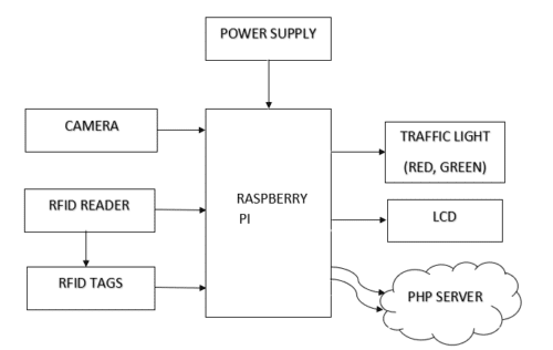
If any car passes the stop signal, the reader will read the tag that violated the rule and will retrieve its information from the database. This project is intended to deliver an intelligent traffic system using radio frequency identification (RFID) technology.
It is designed and implemented in a way where fines are autonomously registered. Low-cost equipment has been used such as RFID technology, passive tags, processing unit (personal computer), and a connection system. First stage is represented by collecting data using the RFID, where it reads any identified tag that attached with vehicles. Next, a certain data is transmitted to the server using internet network communication system[9].
4.2 Method Overview
Requirements
• Raspberry pi 3
• RC522 RFID Reader
• Webcam
• LCD
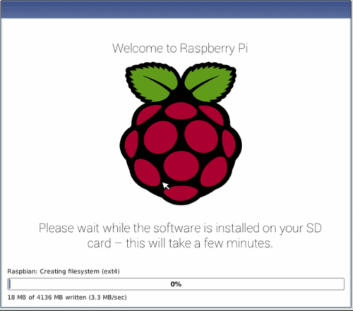
• Raspberry pi OS(desktop), which is installed using NOOBS.
• PHP Web Server scripting language that is embedded in HTML.
Hardware Requirements
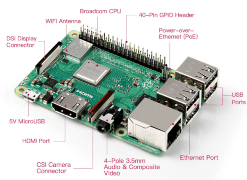
5.1 Raspberry Pi
The Raspberry Pi 3 Model B is a single-board computer developed by the Raspberry Pi Foundation. This board consists of a 1.2Ghz 64-bit quad-core ARM processor and an 802.11n Wireless LAN, Bluetooth 4.1, and Bluetooth Low Energy
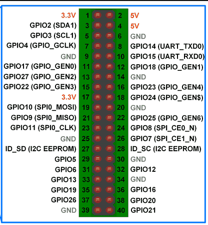
Raspberry Pi-3 Pin Configuration
Broadcom BCM2837:
It is a 1.2GHz 64bit ARM quad-core Cortex A53 processor, with 512 KiB shared L2 cache, dual-core VideoCore IV GPU @ 400 MHz supporting OpenGL ES 2.0, hardware-accelerated OpenVG, and 1080p30 H.264 decode.
GPIO (general-purpose input/output) pins
RC522 RFID Module
The RC522 is a 13.56MHz RFID module that is based on the MFRC522 controller from NXP semiconductors.
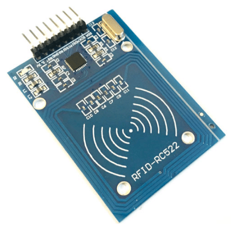
The module can support I2C, SPI and UART and normally is shipped with a RFID card and key fob. It is commonly used in attendance systems and other person/object identification applicationsas shown in the fig:5.3& fig:5.4.
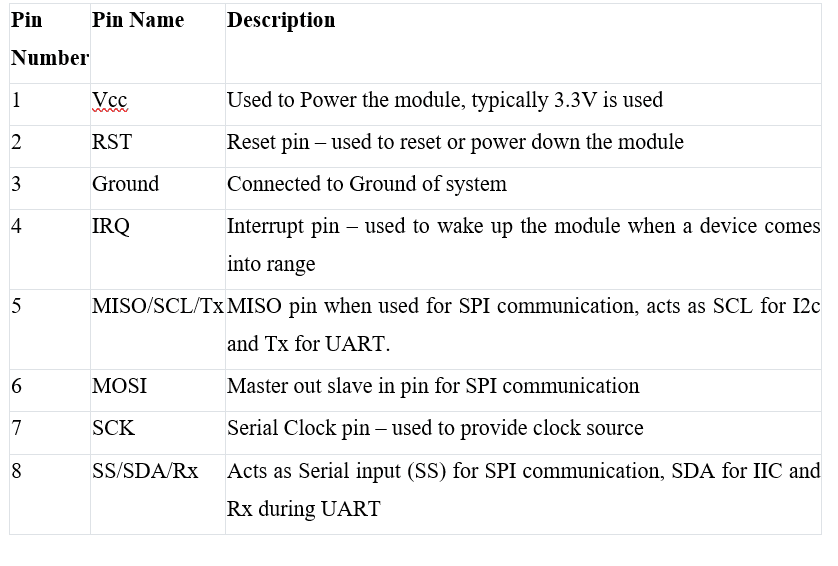
Table 5.2: RC522 Pin description
5.2 LCD
It is one kind of electronic display module used in an extensive range of applications like various circuits & devices like mobile phones, computers, TV sets, etc. These displays are mainly preferred for multi-segment light-emitting diodes and seven segments.
5.3 Light Emitting Diodes (LEDs)
The LED is a special type of diode and they have similar electrical characteristics of a PN junction diode. Hence the LED allows the flow of current in the forward direction and blocks the current in the reverse direction. The applications of LEDs used to make various electrical and electronic projects.
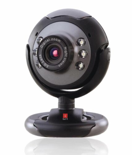
5.4 Web Camera
A webcam is a video camera that feeds or streams an image or video in real time to or through a computer network, such as the Internet. Webcams are typically small cameras that sit on a desk, attach to a user’s monitor, or are built into the hardware. Webcam software enables users to record a video or stream the video on the Internet.
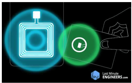
What is RFID technology and how does it work?
RFID (radio-frequency identification) is a technology that employs electromagnetic fields to identify and track tags attached to items. A radio reader, a radio receiver, and a tag make up an RFID system.
RFID Reader
It is a technology that uses electronic identification to confirm the identity, status, and authenticity of vehicle data. It uses radio waves to communicate an object identify. Each object is identified by a serial number that distinguishes it from the others.This RFID reader can be used to track multiple objects at a time [1].
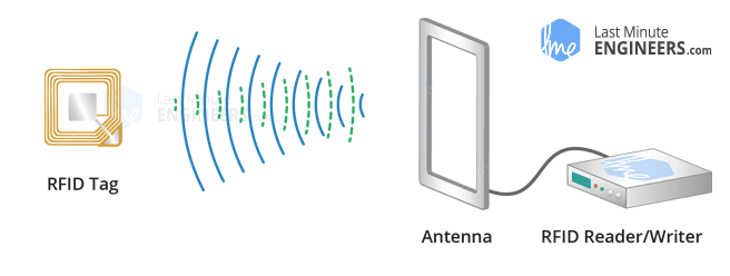
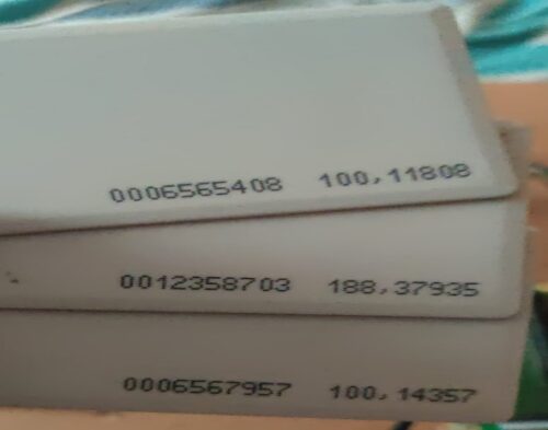
RFID Tag
A Radio Frequency Identification Tag (RFID Tag) is a type of electronic tag that communicates with an RFID reader using radio frequency waves. This RFID reader is continuous sending radio waves, when the RFID tag is in the range of the RFID reader it transmits the feedback signal to the reader [3].
In the vehicle the RFID tag is positioned. A specific number will be given to the RFID tag, and it’ll read with the aid of using the RFID reader and it’ll detect the vehicle as shown in the fig:6.2.[5][8]. The reader will deliver the records to the Raspberry Pi-3 with the use of python software. Raspberry pi-3 will obtain the information from the RFID reader.
Software Requirements
Raspberry Pi OS:
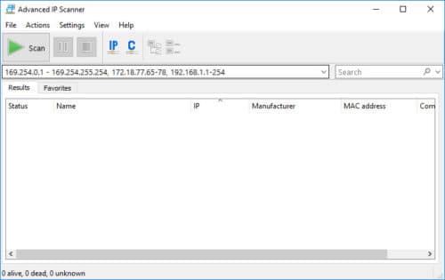
IP Scanner:
Advanced IP Scanner is fast and free software for network scanning. It will allow you to quickly detect all network computers and obtain access to them.
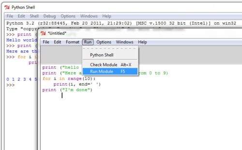
Source Code
import cv2
import RPi.GPIO as GPIO
import serial
import time
import lcd
import urllib
import urllib3
import smtplib
import cv2
camera_port = 0
ramp_frames = 30
from urllib.request import urlopen
urll = ‘http://traffic13968.wizzie.tech/violations.php’#http://traffic13968.wizzie.tech/violations.php
def get_image():
retval, im = camera.read()
return im
def sendemail(ms):
from email.mime.multipart import MIMEMultipart
from email.mime.text import MIMEText
from email.mime.base import MIMEBase
from email import encoders
fromaddr = “[email protected]”
toaddr = “[email protected]”
msg = MIMEMultipart()
msg[‘From’] = fromaddr
msg[‘To’] = toaddr
msg[‘Subject’] = “Alert”#
#body = ‘find below intrader image’
body = ms
msg.attach(MIMEText(body, ‘plain’))
filename = “test_image.png”
#attachment = open(“/home/pi/Desktop/webcam/test_image.png”, “rb”)
attachment = open(“/home/pi/test_image.png”, “rb”)
part = MIMEBase(‘application’, ‘octet-stream’)
part.set_payload((attachment).read())
encoders.encode_base64(part)
part.add_header(‘Content-Disposition’, “attachment; filename= %s” % filename)
msg.attach(part)
server = smtplib.SMTP(‘smtp.gmail.com’, 587)
server.starttls()
server.login(fromaddr, “Chinni98”)
text = msg.as_string()
print (‘Sending Mail’)
server.sendmail(fromaddr, toaddr, text)
server.quit()
print (‘Mail Sent’)
“””
url=(urll+”&field1=”+str(i)+”&field2=”+str(ang)+”&field3=”+”1″)
http = urllib3.PoolManager()
resp = http.request(‘GET’, url)
print(resp.status)
“””
GPIO.setwarnings(False)
GPIO.setmode(GPIO.BOARD)
r1=3
g1=5
GPIO.setup(r1, GPIO.OUT)
GPIO.setup(g1, GPIO.OUT)
GPIO.output(r1, False)
GPIO.output(g1, False)
lcd.lcd_init()
time.sleep(1)
ser = serial.Serial(‘/dev/ttyAMA0’, 9600, timeout=1)
lcd.stringlcd(0x80,”welcome”)
lcd.stringlcd(0x80,”TRAFFIC VIOLATION”)
lcd.stringlcd(0xC0,”CONTROL SYS”)
i = 0
j = 1
while(1):
while i < 10:
GPIO.output(g1, True)
GPIO.output(r1, False)
print(“i”)
print(i)
i=i+1
j=0
time.sleep(1)
string3 = ser.read(12)
#print (string3)
x=string3.decode(“utf-8”)
print (x)
while j<10:
GPIO.output(g1, False)
GPIO.output(r1, True)
string=”
print(“j”)
print(j)
string2 = ser.read(12)
s=string2.decode(“utf-8”)
if len(s) >0:
print (s)
lcd.stringlcd(0x80,”sndng data”)
url=(urll+”?b=”+str(s))
http = urllib3.PoolManager()
resp = http.request(‘GET’, url)
print(resp.status)
lcd.stringlcd(0x80,”sent”)
camera = cv2.VideoCapture(camera_port)
temp = get_image()
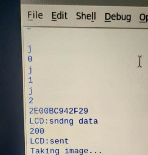
print(“Taking image…”)
camera_capture = get_image()
file =”/home/pi/test_image.png”
cv2.imwrite(file, camera_capture)
print(“capture completed…”)
lcd.stringlcd(0xC0,”capture complted “)
time.sleep(2)
del(camera)
time.sleep(2)
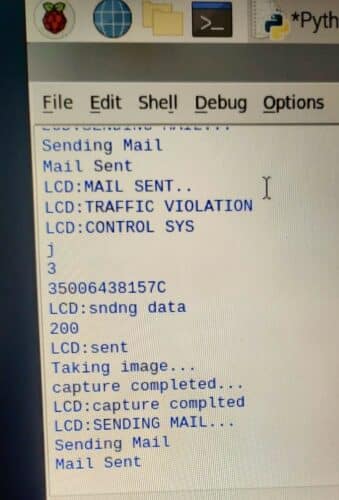
lcd.stringlcd(0xC0,”SENDING MAIL…”)
sendemail(‘Traffic Vilation’)
time.sleep(2)
lcd.stringlcd(0xC0,”MAIL SENT..”)
time.sleep(2)
time.sleep(3)
lcd.stringlcd(0x80,”TRAFFIC VIOLATION”)
lcd.stringlcd(0xC0,”CONTROL SYS”)
j=j+1
i=0
time.sleep(1)
Advantages & Applications
8.1 Advantages
Because only traffic lights are currently automated based on time, the project “Advanced traffic violation control and penalty system” is necessary. Fines are manually assessed and paid in cash or electronically. Because most individuals are unaware of the fee for a particular offence. In the current system, if you are arrested, the cops may take a bribe for a lower sum than the actual fine.
- Automated Penalty Collection for Traffic Signal Violation.
- Less traffic congestion
- Less wasting time and fuel.
- Does not require to be in line of sight.
8.2 Applications
You may need to track the real-time position of assets, staff, or consumers in some applications. RFID solutions enable visibility in any number of areas, whether you’re assessing the efficiency of worker movements, the success of a store floor layout, or tracking the location of key supplies.
Testing Results
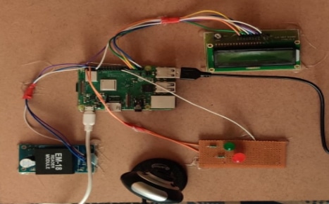
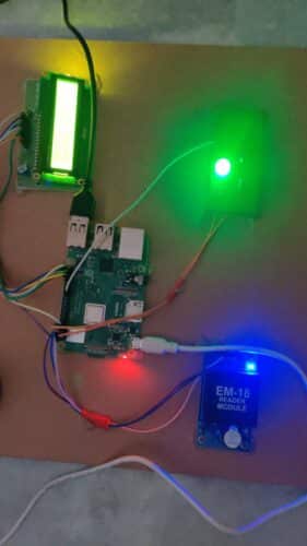
- The hardware board above is connected to the power supply
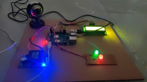
- After running the code, first the green LED will glow
- In the code, the green light is supposed to glow for 10s.
- Now scan the RFID tags on the EM-18 Reader module
- This scanning of the RFID tags with the RFID reader when the green LED is ON represents the vehicle passing the green signal

- As the crossing the green light is not the rule violation there will be no action for this action

- After 10s the Red LED glows and the green LED turns OFF.

- On scanning the tags on the RFID Reader when the red LED is ON, this leads to the rule violation as the vehicle breaks the red signal

- The violation information is notified in the server
- The camera is activated and the image is captured, which can be considered as the proof of the rule violated.
- Now the mail is sent to the rule violator with the information in the server
To Conclude
As a result, we have developed a system that will automatically impose penalties for violations of traffic laws, resulting in more disciplined traffic in our country. We expect that these efforts will aid in the reduction of many traffic-related issues that cause disruption throughout the system, as well as the reduction of the number of accidents, traffic jams that waste our time, and pollution to some level. Our technology only monitors traffic at signal poles, but it may also be used to monitor no-entry zones, one-way routes, and other areas.
Future Work
RFID defence technologies and applications and use of RFID to monitor and track items safely and securing securely in the military supply chain. RFID retail technologies applications which allow retailers to improve on shelf availability increase sales cut labour costs and improve customer care. In healthcare, logistics, manufacturing, Pharmaceuticals etc
K.Geethika, K.V.Sreekar , .Ravi Chandrika, K.Mukesh Reddy Dr. N. Ashok Kumar, B.Tech 5Associate Professor, Department of ECE Sree Vidyanikethan Engineering College,
Tirupati-517102, AndraPradesh