


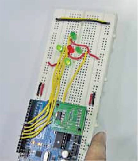
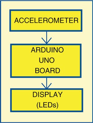
 An accelerometer, which is an electromechanical device, can be used for various applications like tilt detection, obstacle detection, motion inputs, earthquake sensing, etc. Tilt detection is a simple application of an accelerometer where a change in angular position of the system in any direction is detected and indicated through four LEDs. An Arduino Uno board is used to process the data received from the accelerometer and switch on the corresponding LED to indicate the direction of tilt. Fig. 1 shows the author’s prototype and Fig. 2 shows the detector’s block diagram.
Circuit and working
Fig. 3 shows the circuit for the tilt detector. It only requires an Arduino Uno board (Board1), an accelerometer module and few other components.
Accelerometer module
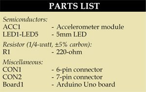
An accelerometer measures acceleration of anything that it is mounted on. The accelerometer module used here is based on ADXL335 triple-axis accelerometer from Analog Devices. The sensor has a full sensing range of ±3 g.

Arduino Uno board
Arduino is an open source electronics prototyping platform based on flexible, easy-to-use hardware and software. It is intended for artists, designers, hobbyists and anyone interested in creating interactive objects or environments. Arduino Uno is a board based on ATmega328 microcontroller. It consists of 14 digital input/output pins, six analogue inputs, a USB connection for programming the on-board microcontroller, power jack, an ICSP header and a reset button. It is operated with a 16MHz crystal oscillator and contains everything needed to support the microcontroller. It is very easy to use as the user simply needs to connect it to a computer with a USB cable, or power it with an AC-to-DC adaptor or battery to get started. The microcontroller on the board is programmed in Arduino programming language using Arduino development environment.
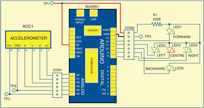
 Pins A0 through A5 of Board1 are connected to pins ST, Z-axis, Y-axis, X-axis, GND and Vcc of the accelerometer module, respectively. The Vcc and GND to the accelerometer module are provided by logic levels at pins A5 and A4. The microcontroller of Board1 receives data for X, Y and Z axes from the accelerometer at pins A3, A2 and A1, respectively. This data is continuously compared with predefined values for each axis. If the received value for any axis crosses the predefined value, a corresponding LED is lit. If the angular tilt is within the threshold limit for each direction, the central LED (red) will glow. Pins 8 through 12 of Board1 are connected to LEDs as shown in Fig. 3.
Download PCB and component layout PDFs: click here
Construction and testing
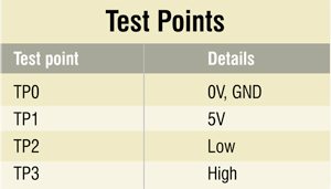
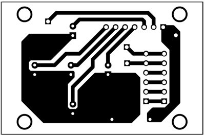
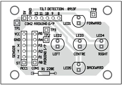
A single-side PCB for the Arduino-based tilt detector is shown in Fig. 4 and corresponding component side layout is shown in Fig. 5. Suitable connectors are provided on the PCB to interface accelerometer and Arduino Uno board. To test the circuit, check the correct voltage levels as shown in the test points table.
For functional testing follow below-mentioned steps:
1. After assembling the circuit, frst we need to trigger values for LEDs, and for that:
(i) Connect the Arduino board to your computer with USB cable.
(ii) Download the source code (test.ino) and burn it on the Arduino board.
(iii) Open the serial port from Arduino environment and press reset button.
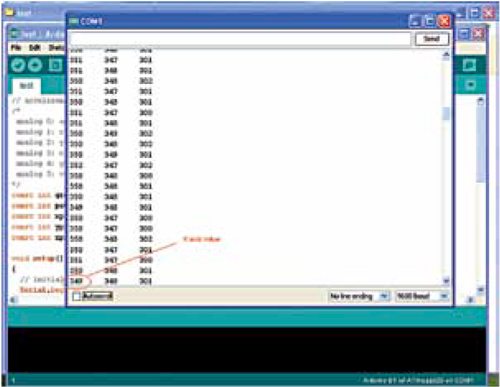
(iv) You will see the screen shown in Fig. 6 on which the values of X, Y, and Z axes will vary corresponding to the position of your accelerometer.
(v) Tilt it to the left and note the value for ‘A_max’ after which you want the corresponding LED to glow. The same trigger will be applied for backward tilt too.
(vi) Tilt it to the right and note the value for ‘A_min’ after which you want the corresponding LED to glow. The same trigger will be applied for forward tilt too.
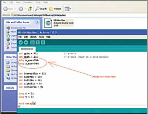
2. The trigger values are defined by ‘A_max’ and ‘A_min’ in the final code (tiltdetection.ino).
3. Download the final code and open it in Arduino IDE.
4. Put the values for ‘A_max’ and ‘A_min’ in the final code as shown in Fig. 7.
5. Program Arduino again with this new code and the system is ready to work.
6. If the angular tilt is within the threshold, red LED will glow. Otherwise LEDs corresponding to each direction will glow.
7. You can see the same on serial port also. Connect the USB and open the serial port in Arduino environment. You will see on the serial port ‘forward’ if tilted forward, and similarly for the other directions.
Software
The software is written in Arduino programming language and the board is programmed using Arduino IDE software. ATmega328 on Arduino Uno comes pre-burnt with a bootloader that allows you to upload new code without the use of external hardware programmer. It communicates using the original STK500 protocol. You can also bypass the bootloader and program the microcontroller through ICSP (in-circuit serial programming) header, but using bootloader is quicker and easier. Select Arduino Uno from the ‘Tools > Board’ menu (according to the microcontroller on your board) in the Arduino IDE and burn the program through standard USB port in the computer.
Download source code : click here
The author is a B.Tech in electronics and communication from Lovely Professional University.