


 An earthquake is an unavoidable and unpredictable natural phenomenon that often causes damage to lives and property. We cannot fight it but we can stay alert and aware using technology that can protect us and the industry. Here a simple earthquake indicator for home and industry using an Arduino and a highly-sensitive ADXL335 (Fig. 1) accelerometer is presented that can indicate vibrations.
This project can be modified and used as a knock-and-shake detector for ATMs, vehicles or door-break alarms. But its main aim is to detect earthquakes and other seismic activities.
We know that accelerometers like ADXL335 are highly sensitive to knocks and vibrations in any of the three physical axes. ADXL335 gives analogue voltage equivalent to imposed acceleration. It has three outputs, one each for of X-, Y- and Z-axes. The three analogue outputs are wired to Arduino Uno ADC pins. Any acceleration caused due to movement in any of the axes is detected by the accelerometer and hence by Arduino ADC.
If motion is violent enough during an earthquake and crosses a certain threshold, a local alarm light (LED) glows, a buzzer sounds as well as a relay energises. While the buzzer and light is for home purpose, relay output is for industrial purpose; it can be wired to a PLC for safety interlocking of any moving machine part and furnace control for shutting these down in case of an earthquake. The threshold adjustment buttons are there for carrying out this task. An LCD has been provided for viewing threshold adjustments and for making the system user-friendly.

Circuit and working
The circuit (Fig. 2) uses Arduino Uno board wired to ADXL335 accelerometer module (connected across CON2) with its ADC inputs, namely, X-axis to A0, Y-axis to A1 and Z-axis to A2. Two pushbuttons through supply of 5V are wired to Arduino Uno interrupt pins 2 and 3 that are pulled down to ground via resistors R2 and R1. These buttons are used for incrementing and decrementing the threshold of vibration detection. A 16×2 LCD (LCD1) is wired in 4-wire mode with Arduino pins contrast control and backlight enabled.
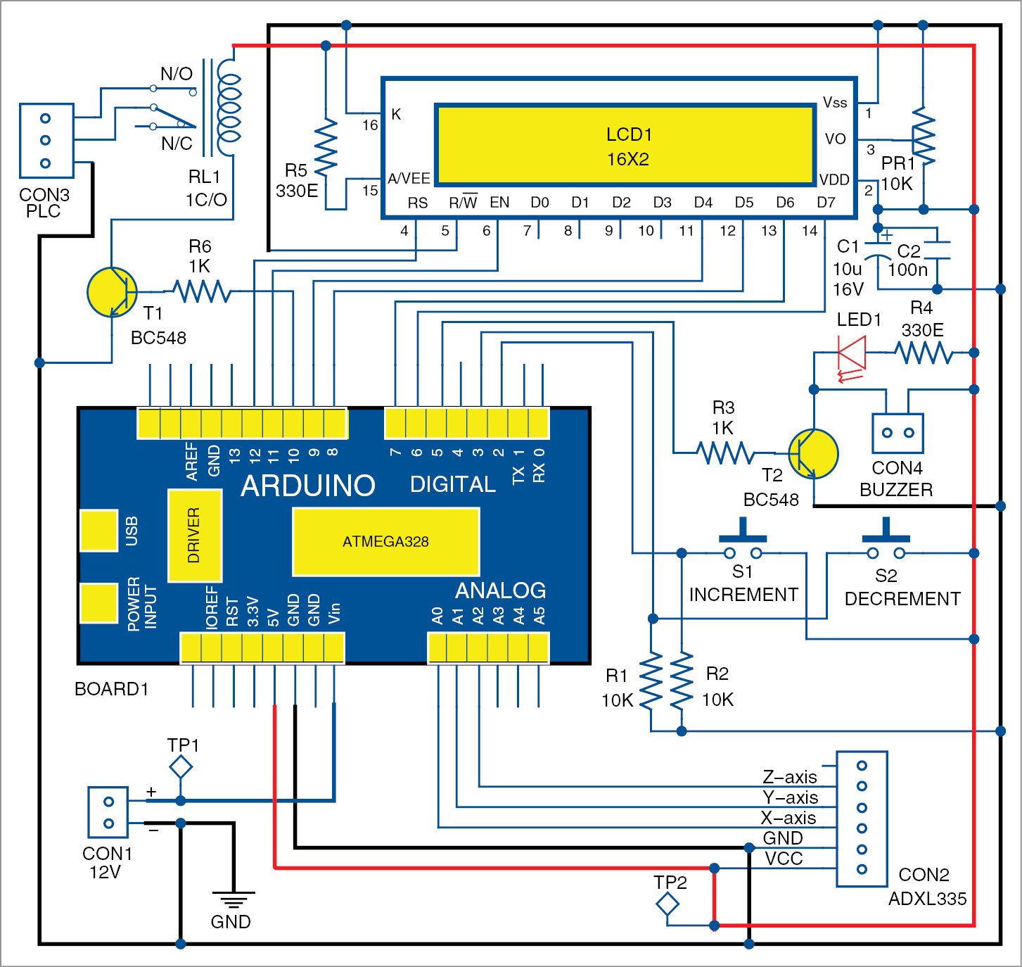

BC548 transistor (T2) is connected to pin 5 of Arduino for switching on the local alarm LED (LED1) and a buzzer connected across CON4. Another BC548 (T1) is connected to pin 10 for de-energising a relay (RL1) in case the alarm is triggered for industrial PLC interfacing for safety interlocks. Pins 11, 12, 9, 8, 7 and 6 are used for LCD control and data lines. When the setup is powered, and while it is still, it reads and stores current accelerometer values in Arduino internal EEPROM regardless of its orientation.
Since the ADC is 10-bit, special header file has been provided with the code. A five-second delay has been provided for all voltages and for the system to be stable before any initial value is read. Arduino’s microcontroller reads all three axes data from the accelerometer and stores in the EEPROM. It also stores the default threshold value of 25 in the EEPROM.
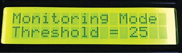
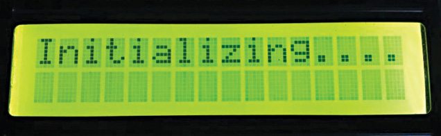
Some conventional indications on the LCD (Fig. 3, Fig. 4 and Fig. 5) are shown here for different working modes. In initialising mode (Fig. 3), system parameters are initialised. In monitoring mode (Fig. 4), the system enters into monitoring mode with current threshold value displayed on the second line of the LCD.
In indicating mode (Fig. 5), the system reads accelerometer values continuously and compares these with previous steady values of the accelerometer, stored in the EEPROM while initialising. If current value differs, that is, if stored value is either more than threshold value in positive side or less than threshold value in negative side, the alarm sounds and the relay is de-energised. This design and coding supports positive as well as negative values in all three axes.
Pushbuttons connected to pins 2 and 3 of Arduino serve as interrupts for incrementing and decrementing threshold values for sensitivity adjustments. For earthquakes, a threshold of 10 to 15 is good. The sensor can also be used to detect knocks and vibrations if the threshold is set to 5 to 8.
The entire setup can be wired and enclosed in a hard enclosure and mounted anywhere in industry or home. Users can also calculate resultant acceleration by using formulae of square root of X2+Y2+Z2, where X, Y and Z are outputs from ADXL335, and then compare the result with the threshold to raise an alarm. Modifications can be done by the user on the same platform, if required.
Software comprises earthQuake.ino with some header files of Arduino.
Download source code: click here
Library File: click here
Ronie Adhiraaj Ghosh is M.Tech from Homi Bhaba National Institute, Mumbai. His hobbies include electronics projects, watch collection, camping and hiking

on compilation it shows that “EEPROMAnything.h” directory doesnt exist. please assist
Dear Shiva Kumar,
We have updated the article with library file.
is there a block diagram for this earthquake indicoter
on compilation it shows that “EEPROMAnything.h” directory doesnt exist. Even in the updated library file can you solve this????
You need to manually add the EEPROMAnything.h file into the library and compile it again. You will not get this error message if you include the file properly.
hi built this as per the schematic
and entered proper codes with the library u sent
but when i start it
it starts with alarm mode
it has never shown me monitoring mode
and how to decrease the sensitivity of the accelorometer adxl335 ?
and yeah i used bc547 is it ok?
becuase most things are normal
now noted one more thing after five minutes of alarm !!!!
please evacuate
the lcd displays some unknown unwanted characters/sentences like
&6_=-kk
4 =
and so on some other language
How can use this circuit?Fitting inside earth?
just dig the land and fit it
The circuit does not work
neither the lcd displays anything nor the beep goes out.
looks like the circuit is faulty.
it works…prototype tested by EFY
i like it, but how do i get the material.
Kindly elaborate your query.
after compiling it shows that
earthQuake.ino:2:28: fatal error: EEPROMAnything.h: No such file or directory
compilation terminated.
Error compiling.
The library file also have been added but still there is error when the program is compiled.
Here’s the reply from author Adhiraaj Ronie Ghosh:
EEPROMAnything.h is a separate library provided with the source code. Before building circuit you shall go through the write up properly. Copy the header file in arduino library and then compile.
Hi there is is possible to get a full report on this project please.
the price of industrial PLC is very high. Can i use any alternate device instead of PLC?
it working well
thanx for the circuit
You are welcome.
Hi,
I built it and it’s working nice. If I set the threshold to 15 with the buttons it’s working nice but
the setting return to 25 at each reboot. Is it possible to store the adjust settings in the EEPROM ?
Thanks,
I want to buy this project.. how can i get it??
Compiling error eeprom read anything was not declared in this scope
Hi can you provide us the list of materials thank you :)) for a project
Very interesting. Can you provide us the list of materials sir? I really need for our project :'(
Will it work for security awareness??
yes, can be used on doors to detect break in
can this system be used to detect landslides too
please suggest me a software to do this
HI. where the coding for this project?
The source code is present at the end of the article.