


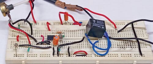
 Often streetlights remain on till late in the morning and are not switched on as soon as it gets dark. This circuit will automatically turn off a streetlight at dawn every morning and switch it on again at dusk each evening. The author’s prototype is shown in Fig. 1, while its circuit diagram is shown in Fig. 2.
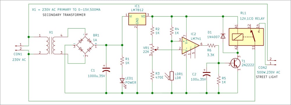
The circuit has a step-down transformer (X1), a bridge rectifier (BR1), a 12V voltage regulator 7812 (IC1), op-amp LM741(IC2), a 12V single-changeover relay (RL1), and a few other components. Capacitor C1 connected across the supply terminals minimises ripples and any other noise signals.

The circuit works on 12V DC, which is obtained from the 230V AC primary to 15V, 500mA step-down transformer X1. The 230V AC mains is connected to the primary of X1 via CON1 in the circuit. The transformer’s 15V AC secondary is connected to bridge rectifier BR1 for rectification of the voltage, which is filtered by capacitor C1. The rectified and filtered voltage goes to IC LM7812 to get regulated 12V DC voltage for the circuit.
| Parts List |
| Semiconductors: IC1 – LM7812, 12V voltage regulator IC2 – LM741 op-amp T1 – 2N2222 NPN transistor BR1 – 1A bridge rectifier D1 – 1N4007 rectifier diode LED1 – 5mm LED Resistors (all 1/4-watt, ±5% carbon): R1, R2, R4, R5 – 1-kilo-ohm R3 – 470-ohm R6 – 3.3-kilo-ohm VR1 – 2.2-kilo-ohm pot Capacitors: C1 – 1000μF, 35V electrolytic C2 – 100μF, 35V electrolytic Miscellaneous: CON1, CON2 – 2-pin connector RL1 – 12V, 1C/O relay X1 – 230V AC primary to 15V, 500mA secondarytransformer – 500W, 230V streetligh |
Heart of the circuit is op-amp LM741 in 8-pin DIP package. Here it is used as a comparator and not as an amplifier. It compares the input voltage (Vin) with the reference voltage (Vref). When Vin rises above or falls below Vref, the output changes accordingly.
The reference voltage Vref is provided at inverting input (pin 2) of the IC through divider network built around resistor R2, pot VR1, and resistor R3. The input voltage goes to the IC’s non-inverting input (pin 3) through the divider network comprising resistor R4 and light-dependent resistor LDR1. Pot VR1 is used for setting the reference voltage.
Light-dependent resistor is a special type of resistor whose value changes with the intensity (brightness) of light falling on it. It has resistance of about 1-mega-ohm when in total darkness, but a resistance of only a few kilo-ohms in bright sunlight. It responds to a large part of the light’s spectrum.
Working of the circuit is simple. As soon as power is switched on, LED1 glows. In daytime, when light falls on LDR1, the input voltage at pin 3 of IC2 is low as compared to the reference voltage at pin 2, so output at pin 6 of IC2 is also low. Relay RL1 does not energise in this condition and the streetlight remains off.
As night approaches, light falling on LDR1 reduces. At some point, input at pin 3 of IC2 becomes higher than the reference voltage at pin 2, so output at pin 6 of IC2 goes high. Now relay RL1 energises via relay driver transistor T1. As a result, the streetlight gets 230V AC and switches on.
The streetlight remains on till dawn but in the morning, when sufficient light starts falling on LDR1 once again, relay RL1 de-energises and switches off the streetlight. Thereafter, the cycle repeats each day.
Construction and testing
A single-side PCB layout for the automatic streetlight is shown in Fig. 3 and its component layout in Fig. 4. After assembling the circuit on PCB, enclose it in a suitable box. Fix LED1 in front of the box and connector CON2 on its rear side to connect to the streetlight.
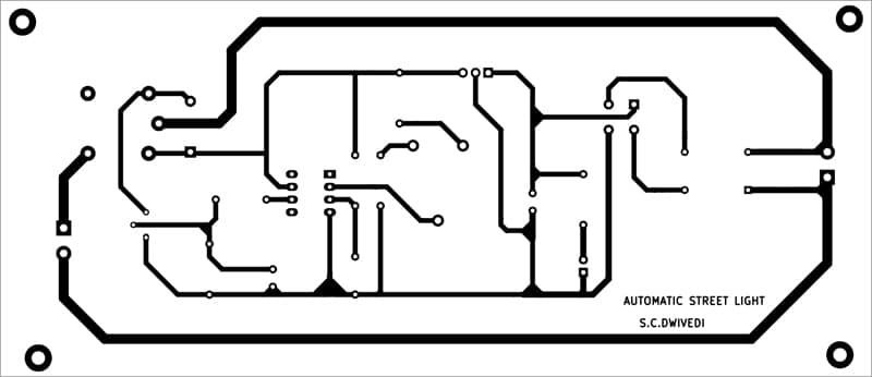
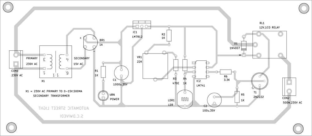
Download PCB and Component Layout PDFs: click here
Proper installation of the assembled circuit box is very important. Install the circuit box on the streetlight pillar is such a way that normal daylight falls on LDR1 but light from the streetlight does not fall on it. After proper installation, connect 230V AC mains voltage across CON1. The circuit is now ready to use automatically.
We have one more street light controller that you might check
Bonus. You can watch the video of the tutorial of this DIY project at: click here

Sir, Instead of capacitor C2, can we add a hysteresis resistor in the op-amp LM741?
No, You can not use resistor in place of C2.