


 Voltage fluctuations and power cuts can damage electrical equipment and goods like submersible pumps, air-conditioners, television sets, and refrigerators. The Appliances Protection circuit presented here (see Fig. 1) will protect the costly electrical items from high as well as low voltages.
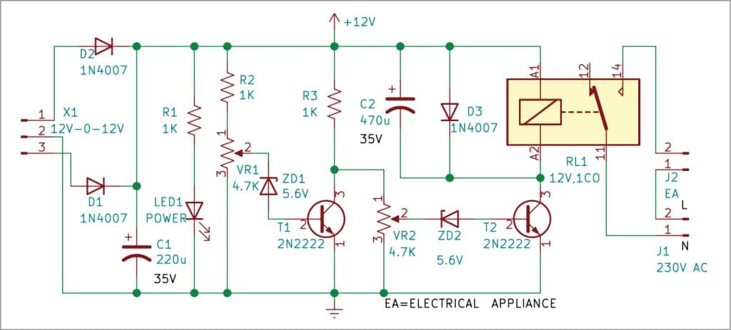
The circuit comprises step-down transformer X1, 2N2222 transistors T1 and T2, 1N4007 rectifier diodes D1-D3, a 5mm LED (LED1), 5.6V Zener diodes ZD1 and ZD2, 4.7k potmeters VR1 and VR2, 12V single-changeover relay RL1, and a few other components.
The circuit works on 12V power supply derived from 230V AC primary to 12V-0-12V, 500mA secondary step-down transformer X1. Diodes D1 and D2 rectify the AC into pulsating DC, which is smoothened by the 220µF, 35V filter capacitor C1 to produce a regulated 12V DC voltage to operate the circuit. This 12V voltage increases or decreases slightly based on higher or lower than the normal 230V supply of AC mains input received through transformer X1.
 When the AC mains voltage is between the normally-acceptable range of 190V and 230V, the DC voltage at cathode of Zener diode ZD1 is less than 5.6V. As a result, transistor T1 is non-conductive. At the same time, DC voltage at the cathode of Zener diode ZD2 is more than 5.6V. So, transistor T2 is in conduction mode. Consequently, relay RL1 energies and electrical appliance connected at its contacts gets the AC power supply.
When mains voltage goes high, say more than 230V AC, transistor T1 conducts because voltage at cathode of Zener diode ZD1 becomes greater than 5.6V, and transistor T2 does not conduct. As a result, relay RL1 de-energises and electrical appliance gets disconnected from the AC mains power supply to protect the appliance.
If the mains voltage becomes low, say less than 190V AC, transistor T1 does not conduct because voltage at cathode of Zener diode ZD1 is less than 5.6V. So, transistor T2 also does not conduct. As a result, relay RL1 de-energises and electrical appliance once again gets disconnected from the mains power supply.
To avoid chattering of relay RL1, especially during high/low voltage threshold level settings, capacitor C2 is connected across the relay coil.
Construction and testing
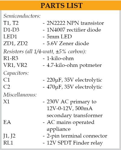
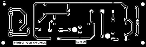
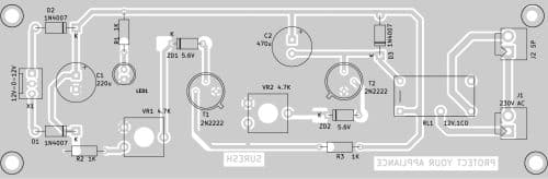
An actual-size PCB layout for the circuit is shown in Fig. 2 and its component layout in Fig. 3. After assembling the circuit on PCB, enclose it in a suitable plastic box.
Connect the electrical appliance to connector J2 and 230V AC mains to connector/socket J1. The AC mains socket should be fixed at the back side of the cabinet to connect the electrical appliance.
Connect LED1 and potmeters VR1 and VR2 on the front of the cabinet. VR1 and VR2 are used to set the low and high voltages, respectively, to trigger the circuit for protection of appliances.
Download PCB and Component Layout PDFs: click here
S.C. Dwivedi is an electronics enthusiast, circuit designer and technical article writer
A relay doesn’t respond that fast and sometimes, by the minute a surge comes in, it turns everything off only aftet your circuit is burn.. i suggest using an optocoupler..
No error in D3 diode connection?
Dear Chris,
There is a mistake.Please revers the polarity of diode D3.
Hope it should work.
Thanks for pointing out the mistake.
Regards
Dear Nazmi,
Yes, cathode of D3 should connect to 12V and anode to
collector of transisor T2.
Thanks for pointing out the mistake.
Regards