


 In a boiler safety project, we collect 32 thermocouple readings from the depth of a 500MW boiler second pass area, where ambient temperature on a normal day is 65 to 70°C due to hot area leakages in the vicinity. However, the thermocouples need to measure temperatures ranging from 350 to 150°C, depending on their positions.
During a boiler shutdown, we fixed the thermocouples in their strategic places, connected an Arduino Mega board, fixed the LoRa radio with only its antenna sticking outside the IP64 cabinet, and then fixed the box on a post. The 220V AC supply from a nearby pillar was converted through a smartphone adaptor to 5V DC and introduced into the cabinet through a small hole below it.

The two sets of 16 each K-type thermocouples having 32 wires were introduced into the two boxes through side slots, which were then sealed with special insulating putty and m-seal. The thought of providing an LED indication to show health of these devices was turned down as hardly anyone visits the place at this height and high temperature. We finally have two black boxes fixed on a pillar with 32 thermocouple cables entering each box.
Who uses this data?
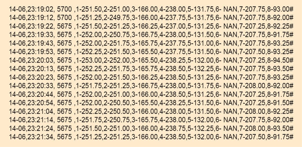
All the data goes every ten seconds to a nearby service building situated a good 700 metres away where the boiler maintenance team has their office. The small handheld Arduino Mega device, besides storing the data in CSV format, shows it on a small TFT screen in four columns. It also has capabilities to demonstrate the rate-of-rise of temperature with audio/visual alarm. The data arrives in a CSV format, as shown in Fig. 2.
The data was being monitored by the boiler maintenance department as they are the sole agency to take care of any abnormalities of the parameters. But one day an important aberration occurred when the maintenance staff was on holiday. So, it was decided that the data should be posted on LAN/WAN so that it could be monitored round-the-clock by the 24×7 local operation department and regional operation centre.
While the IT department started exploring several protocols like telnet, wget, ftp, web database, etc, I suggested uploading it to a cloud wherefrom it could be accessed by all. But doing it on Arduino Mega is a challenge, though not impossible.
| Bill of Material |
|
1. Arduino Uno R3 -1
2. Motor driver shield -1 3. Wheels -4 4. DC gear motors -4 5. Servo motor -1 6. Ultrasonic sensor -1 7. Sensor stand -1 8. Lipo battery -1 9. Acrylic sheet -1 10. Male and female jumper wires |
ESP32 LoRa router
Its rather easy to achieve this feat through ESP32. The UART LoRa radio is first to be connected to the receiver/transmitter of the ESP32. While softwareserial works on Arduino, only hardwareserial works on ESP32. Therefore, the LoRa radio needs to be connected on the hardware serial port first. For setting hardwareserial on ESP32, the following command is used:
Serial1.begin(9600, SERIAL_8N1, RXD1,
TXD1); //
Serial2.begin(9600, SERIAL_8N1, RXD2,
TXD2); //
// For Rx = 16,15,13,34
// For Tx = 17,12,4,35
You can set your own pins for the transmitter and receiver. The abovementioned pins worked splendidly. For connecting two LoRa radio units two UART sets can be used. As per data book, ESP32 can have three UARTs at a time and any GPIO pin can be set for serial communications.
Once the LoRa radios start communicating with the ESP32 on the UARTs, the next step is of setting up the Wi-Fi network for connecting with the internet. This crucial part of networking can be done through the command:
#include <WiFi.h>
#include <WiFiUdp.h>
#include <HTTPClient.h>
#include <esp_wifi.h>
const char *ssid = “bera1”;
const char *password = “**********”;
const char *ssid1 = “bera2”;
const char *password1 = “**********”;
I have two networks to use and, depending on the connectivity, the ESP32 is programmed in such a way that if it does not get the connection, it looks up its EEPROM memory and restarts to connect to an alternate network. You can provide any number of ssid and passwords and, in case it fails to connect, the ESP32 will try all of them one after the other. Of course, small changes for additional network selection criteria would need to be adopted in the setup area.
When the ESP32 starts getting data at the SS radio network and is connected to the internet using Wi-Fi or BLE (Bluetooth Low Energy), if we can transfer the data from one network to the other, the ESP32 will achieve the status of a router. At this point we can select our own server or cloud, or we can find a third-party server or cloud. Since our company’s cloud is in the making, we decided to upload eight sets of very critical data to a public cloud for distribution and visibility for everyone. The data is available at following site at present: https://thingspeak.com/channels/279012
Circuit and working
The pin connections of the ESP32 LoRa gate are shown in Fig. 3. The connection between LoRa module and ESP32 board are made as following:
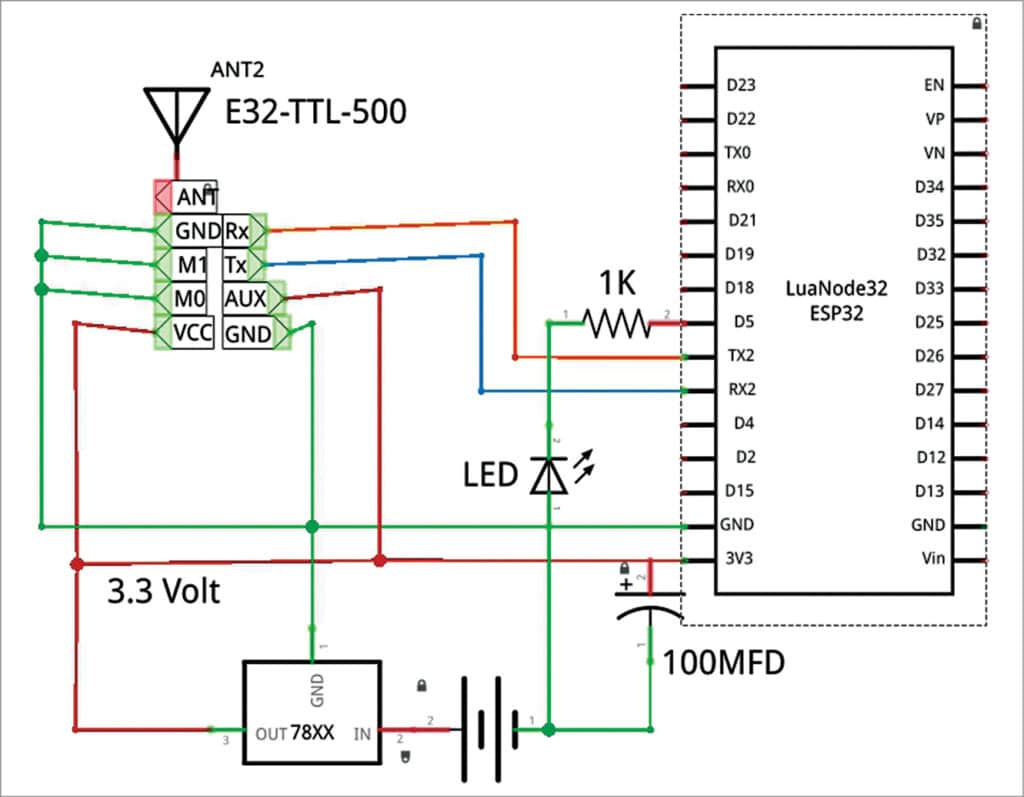
- ESP32 pin 16 to Tx of LoRa, ESP32 pin 17 to Rx of LoRa
- LoRa M1, M2 to ESP32 GND pin
- LoRa Aux to +ve pin of ESP32 (3.3V)
- LoRa GND to ESP32 GND
- LoRa -ve to +ve pin of ESP32 (3.3V)
The ESP32 gets data on its Tx2, Rx2 (17,16) vide SS radio interface and, after connecting to Wi-Fi, sends it to internet servers. It is not necessary to upload the data on a public cloud only. It can also be sent to a personal or corporate server. The following site can be used to upload data to a LAMP server using ESP32/ESP8266: https://electronicsforu.com/electronicsprojects/software-projects-ideas/distributed-cloudcomputing-esps
For uploading data to thingspeak server, one needs to have an API upload key, which may be obtained after registering with the thingspeak.com site. After having the API key, the sensor data is lined up in a string, which is then parsed through the following:
http.begin(poststr);
int httpCode=http.GET();
if (httpCode > 0) { //Check for the returning code
String payload = http.getString();
Serial.println(“Updated”);
}
Construction and testing
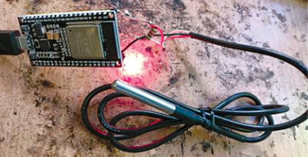
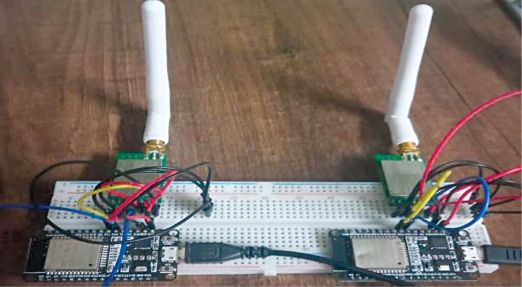
We have used two ESP32s, which are connected to two different laptops, as shown in Fig. 4. To each of the ESP32 a LoRa module is connected with suitable wire connections.
Softwareserial works only on Arduino, and hardware serial works only on ESP32. Hence, the module is connected on the hardware serial port. As we are validating the original design, the number “3456” was given as the number to be sent from the sender. The number was initialised in the character data type. Refer the screenshot shown in Fig. 4.
So, after sending the number “3456” from the sender node, we first verify if the data is reaching the receiver. In the serial monitor of the receiver the number “3456” was being displayed, hence establishing the fact that the two modules are communicating with each other. The baud rate was set to 115200. We need to configure the serial monitor to the same baud rate in order to see the received data.
After verifying that the data is successfully being relayed to the receiver, we can use the internet to upload this received data onto the ThingSpeak server. ThingSpeak is a cloud based IoT analytics platform, which has integrated support from MATLAB. In ThingSpeak, the received data can be viewed in the CSV format as well, among the different types of compatible formats. ThingSpeak has visual tools, which helps us to see the flow of data with respect to time. It also has a numerical visual tool, which helps us to see the number being received by the receiver and sent to ThingSpeak.
Every user on ThingSpeak can make channels for their data. Every channel has a unique channel number and an API key, and these are used as channel identifiers. The receiver node has to be connected to the internet in order to upload data onto the server. After connecting the receiver ESP32 to the internet, the code starts pushing the received data onto the server. The code uses HTTP GET to request the JSON, after which the data gets uploaded onto the server. The HTTP status code of 200 indicates that our request has been accepted.
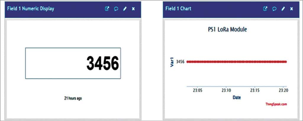
With the help of the elaborative widgets on the ThingSpeak interface, a real-time view of the data transfer can be seen graphically. We may verify that the number “3456” is being displayed on both widgets of the ThingSpeak server, thus confirming that the data has reached the server.
The downloaded data in CSV format includes timestamps, according to one’s time zone. The GMT time zone is used as default for this. The CSV files show the time-wise arrival of data on the server.
Somnath Bera is an electronics and IoT enthusiastic working as General Manager at NTPC