


 Here is a low-ripple and low-noise 48V regulated phantom power supply for an audio preamplifier and driver. Such power supplies require well-filtered, low-ripple and low-noise output voltage with current less than 200mA. These are relatively rare and expensive. Presented here is a simple and low-cost solution suitable for many applications including test equipment and audio applications.
Circuit and working
The circuit diagram of the 48V regulated power supply with low ripple and low noise is shown in Fig. 1. It is built around bridge rectifier BR1, voltage regulator TL783 (IC1), three rectifier diodes 1N4004 (D1 through D3) and a few other components.
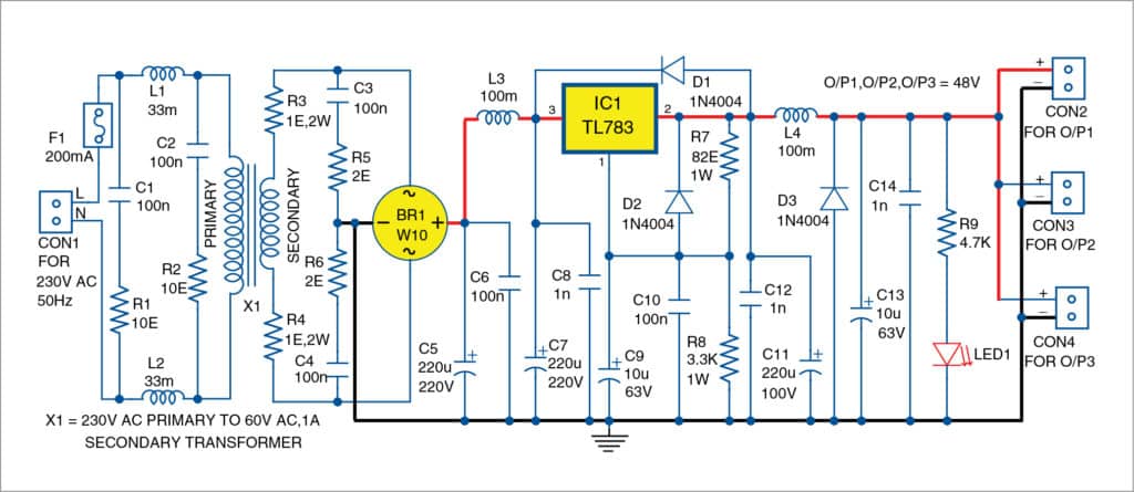
TL783 is a high-voltage adjustable voltage regulator that can provide voltage from 1.2V to 125V and output current up to around 700mA. Its internal reference voltage is 1.25V, and minimum output current is 15mA. That is why the value of resistor R7 is 82ohm (1.25V/82ohm=15.24mA).
Maximum power dissipation of TL783 depends on TO-220 package and its heat-sink. Here, an additional heat-sink with thermal resistance lower than 10°C/W is used. Output voltage of TL783 can be calculated using the approximate relationship:
Vout=1.25V×(1+R8/R7)
Input 230V AC mains is applied to connector CON1.
AC mains input is protected with fuse F1. Mains AC voltage may have significant noise. Input noise filter is built around capacitors C1 and C2, resistors R1 and R2, and inductors L1 and L2.
Transformer X1 is rated as 230V AC primary to 60V, 1A secondary.
Resistors and capacitors R3, R4, C3, R5, C4 and R6 provide some filtering of the noise from AC mains and from the switching of diodes in BR1. Capacitors C5, C6, C7 and C8 filter the rectified voltage. Also, C9 and C10 reduce the noise from IC1. Diodes D1, D2 and D3 protect IC1. Resistors R7 and R8 fix output regulated voltage Vout. Inductor L4 and capacitors C13 and C14 further filter output voltage from IC1.
The circuit has three outputs (O/P1 through O/P3), with 48V phantom power supply from each to drive up to three different circuit applications. LED1 shows the presence of output voltage.
Construction and testing
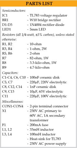
A PCB layout for the 48V regulated power supply is shown in Fig. 2 and its components layout in Fig. 3. After assembling the circuit on the PCB, enclose it in a suitable cabinet.
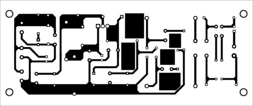
Fix transformer X1 on the body of the cabinet, and connect its primary and secondary on the PCB. Also, connect 230V AC mains across CON1. Fix LED1 on the front panel, and CON2 through CON4 on the rear side for the output loads.
The circuit does not need any adjustment to operate properly.
Petre Tzv Petrov was a researcher and assistant professor in Technical University of Sofia (Bulgaria) and expert-lecturer in OFPPT(Casablance), Kingdom of Morocco. Now he is working as an electronics engineer in the private sector in Bulgaria.
For reading other interesting DIY Projects: click here