


 The circuit presented here uses a joystick to control a robot. A joystick is more comfortable to use and accurate to control a robot as compared to switches.
The circuit is simple, compact and low-cost. It uses two ATtiny13A (eight-pin) microcontrollers (MCUs) for both transmitter and receiver circuits.
The circuit of the joystick-controlled robot comprises a transmitter and a receiver.
Transmitter. The transmitter circuit shown in Fig. 1 is built around joystick module, fixed 5V voltage regulator LM1117-5.0 (IC1), ATtiny13A MCU (IC2), 433MHz RF transmitter module (TX1) and a few other components.

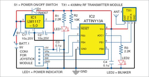
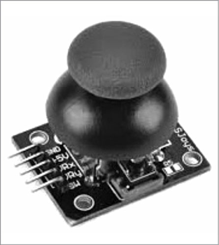
The joystick module, shown in Fig. 2, provides x-axis and y-axis control through a switch. Status of joystick movement is read by ATtiny13A MCU, which transmits the status as serial data of eight bits wirelessly through TX1.
The transmitter section gets 5V DC power supply from 9V battery through 5V regulator IC1.
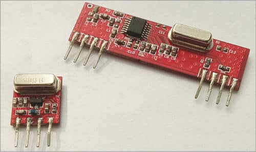
Images of 433MHz RF transmitter and receiver modules are shown in Fig. 3.
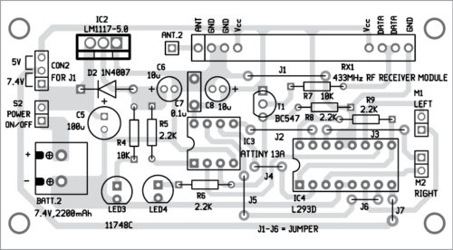
Receiver. The circuit diagram of the receiver section is shown in Fig. 4. It is built around fixed 5V voltage regulator LM1117-5.0 (IC3), ATtiny13A MCU (IC4), 433MHz RF receiver module (RX1), motor driver IC L293D (IC5), two 5V – 7.4V battery-operated geared motors (M1 and M2) and a few other components.
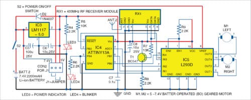
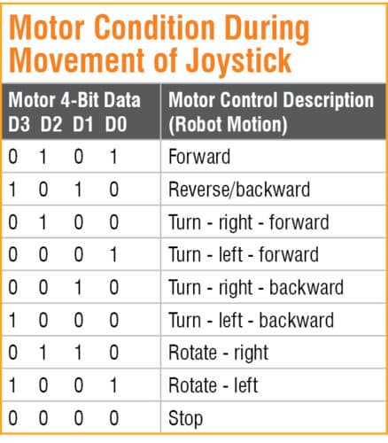
The receiver circuit contains another eight-pin ATtiny13A MCU (IC4). It receives eight-bit transmitted data through RX1 and then sends parallel four-bit data (D3 to D0) to IC5. It contains an H-bridge to control motors of the robot. It is powered by two power supplies, 5V and 7.4V, via jumper J1 to drive motors M1 and M2. J1 is used to select 5V motor voltage or 7.4V battery voltage.
5V regulator IC3 is used for the MCU and RX1. The 5V power supply is derived from 7.4V lithium-ion or 7.4V lithium-polymer batteries. Here, 7.4V lithium-ion battery is used.
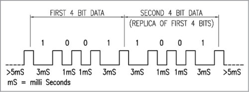
Data transmitted from the transmitter section contains eight bits of serial data; last four bits are a replica of the first four bits. This concept is useful to cross-check the correctness of received data in the receiver section. ATtiny13A does not have serial data transmission pins; hence, a separate coding is developed for serially transmitting and receiving using ATtiny13A (like PWM concept), which is explained below.
Logic low (zero)=signal is one millisecond off with prefix one millisecond on. Logic high (one)=signal is three milliseconds off with prefix one millisecond on. Logic start (or reset)=signal is five milliseconds or more off with prefix one millisecond on. Refer Fig. 5.
Software
The source code is written in C language. Function sendCode is used in JoystickTx.C to transmit the code, while loop in JoystickRx.C continuously monitors the signal and then sends the proper four-bit data to IC L293D to control the motors.
Accordingly, JoystickTx.hex is generated to burn it into ATtiny13A (IC2) and JoystickRx.hex to ATtiny13A (IC4). For burning the codes, you can use any suitable ATtiny13A programmer.
Construction and testing
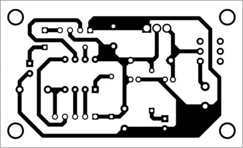
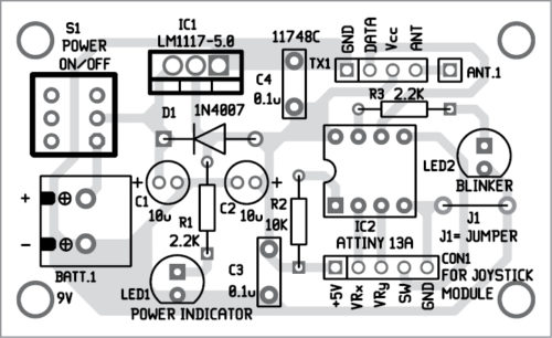
A PCB layout of the transmitter section is shown in Fig. 6 and its components layout in Fig. 7. Assemble the circuit on the PCB. Connect the joystick module across connector CON1 using external jumper wires. Power supply for the transmitter is provided by 9V battery.
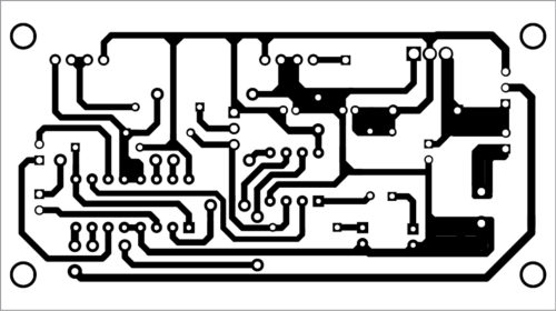
A PCB layout of the receiver section is shown in Fig. 8 and its components layout in Fig. 9. Make all jumper connections using external wires. Assemble the circuit on the PCB. Power supply for the receiver is provided by 7.4V lithium battery.
Download PCB and Component layout PDFs: click here
After assembling the circuits on transmitter and receiver PCBs without RF modules, burn/write JoystickTx.hex and JoystickRx.hex on the respective ATtiny13A MCUs using a suitable AVR programmer. Then, mount the MCUs on the respective PCBs.
Connect signal output pin 6 of ATtiny13 of the transmitter board and signal input pin 3 of ATtiny13 of the receiver board without connecting RF modules. Ground pins of both the boards must be connected.
Now, power on both boards. Observe blinker LED2 on the transmitter board. It blinks whenever data bits are correctly transmitted in the loop. Blinker LED4 on the receiving board blinks whenever motor movement data is received.
Next, test movement of the motors using the joystick. If motors are not rotating, check voltage status of D3 to D0 (pins 2, 7, 6 and 5) of ATtiny13A at the receiving board using a voltmeter (or an LED with 2.2-kilo-ohm resistance in series). Then, check connections of the motors and L293D. To change direction of rotation of the motors, interchange the wire connections on the receiving board as per requirement.

If everything is alright, power off both the boards. Remove the connecting wires between transmitter and receiver boards. Connect RF modules on the transmitter and receiver boards, and test for RF connectivity.
Fix the receiver unit on chassis of the robot along with the wheels. M1 and M2 are fixed on the chassis along with a castor wheel at the front of the robot. Keep the transmitter unit and the joystick with you to control the robot. Now, you can control the robot using the joystick from a distance of up to thirty metres; the range depends on RF modules.
Fayaz Hassan is a manager at Visakhapatnam Steel Plant, Visakhapatnam, Andhra Pradesh. His interest includes MCU projects, mechatronics and robotics.
What a scheme if there is no software code?
The project will not work without software code. You can download the code from here: https://efy.efymag.com/admin/issuepdf/Make%20this%20joystick-controlled%20robot.zip