


 Most shunt resistors have values below one ohm. Such low values of resistances cannot be measured reliably due to range and resolution limitation of the measurement devices. These are usually measured using resistance bridges that require a special setup.
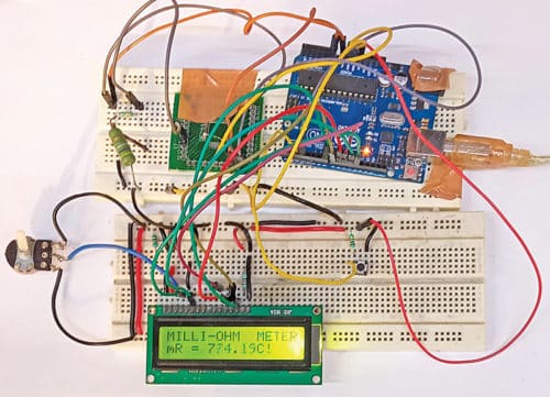
Presented here is a circuit that can measure resistances of 0.1-ohm to 1-ohm. EFY lab’s prototype of the milli-ohmmeter is shown in Fig. 1.

Circuit and working
Circuit diagram of the milli-ohm meter is shown in Fig. 2. The circuit is built around Arduino Uno board (Board1), low-dropout regulator MIC5219 (IC1), and 16×2 LCD display (LCD1).
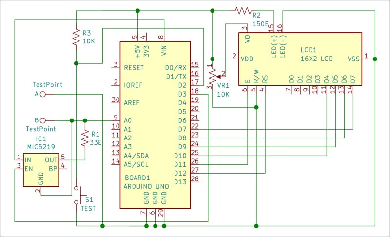
When current passes through a resistor, a voltage drop occurs across the resistor in proportion to the current passing through it. By using this principle, known as Ohm’s Law, the resistance is measured by using this circuit.
The resistance to be measured is connected across test points A and B in the circuit. The voltage drop across the resistor appears at analogue pin A0 of the Arduino board. The analogue reference voltage is changed to internal 1.1V reference for better resolution.
The Arduino Uno is the brain of this circuit that calculates the resistance based upon the analogue-to-digital (ADC) value and displays it on the LCD. IC1 is configured as a constant-current regulator.
When the push-to-on switch S1 is pressed, IC1 is enabled by the Arduino, and it supplies constant current of 100mA across the test resistor. A voltage drop occurs across the test resistor whose resistance is calculated by the Arduino using Ohm’s Law and it is displayed on LCD1.
The resistance to be measured should not be more than one ohm. If it is more than one ohm, ‘!OL OR NC!’ message will appear on the LCD1.
Also, whenever the resistance value is beyond the one-ohm limit, it is disconnected from the circuit. If S1 is pressed again after measurement, IC1 is disabled.
Arduino Uno is a popular open source microcontroller development board based on Atmega328P microcontroller. It has fourteen digital input/output (I/O) pins of which six can be used for PWM outputs and six for analogue inputs. A 16MHz crystal, USB connector, power jack, and ICSP header can also be connected to it. It comes with preloaded Arduino bootloader, so there is no need of additional hardware to burn the Atmega chip.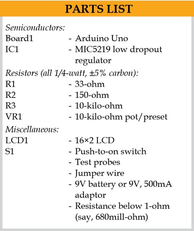
The circuit uses the software program loaded into the internal memory of Arduino Uno for operation. The program mR_Meter.ino is written in Arduino programming language known as Sketch. An Arduino IDE is used to compile and upload the program.
Construction and testing
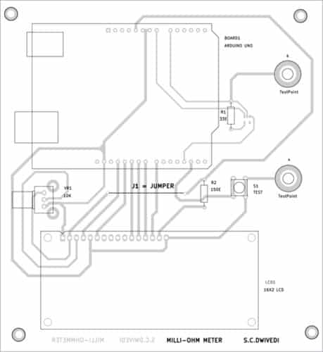
An actual-size, single-side PCB for the milli-ohm meter is shown in Fig. 3 and its component layout in Fig. 4. Before using the circuit, do not forget to upload the source code mR_Meter.ino by burning it into the microprocessor in Arduino Uno board.
After assembling the circuit on PCB, enclose it in a suitable box. The test switch S1 should be fixed at a convenient position in the cabinet so that it can be used easily.
The Arduino Uno can be powered by a 9V battery or a 9V, 500mA adaptor. Use a suitable connector for test points A and B for connecting the test resistance to be measured.
Download PCB and Component Layout PDFs: click here
EFY notes
- This circuit measures low resitances of 0.1-ohm to 1-ohm only. There may be an error/deviation in the measurement due to parasitic elements in the PCB.
- Any other suitable low dropout regulator (LDO) can be used in place of MIC5219 for IC1.
-
A 1.5V Zener diode can be connected across the analogue pin and ground to bypass the current source if no resistance is connected when the LDO is enabled by the Arduino.
A. Samiuddhin, a circuit designer, is B.Tech in electrical and electronics engineering. His interests include LED lighting, power electronics, microcontrollers, and Arduino programming
Hi , Thanks for project
You are most welcome.
Very interesting .
I ask for the possibility of receiving the sketch for arduino
Thank you
Greetings
Vincenzo
favor passar o SKETCH arduino , milli-ohm-meter-with-0-1-to-1-ohm-range
Kindly write your comment in english.