


 This unique but simple call bell can be used to call an office boy or a help at home from up to nine different places. Besides ringing, it shows the number of caller’s room or place from where the call is being made.
Full Video Explaination:
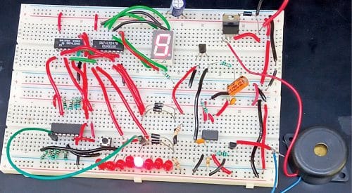
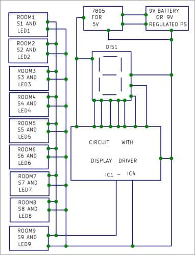
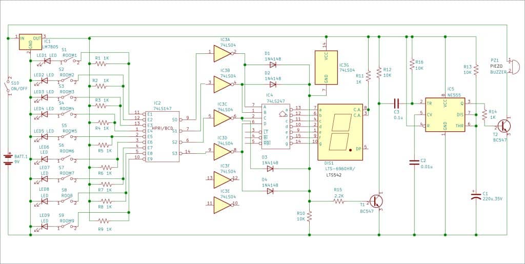
The author’s prototype is shown in Fig. 1 while its block diagram is shown in Fig. 2. The call bell is built around LM7805 voltage regulator IC1, ICs 74LS147, 74LS04, and 74LS247 (IC2-IC4), NE555 timer IC5, BC547 transistors T1 and T2, and 1N4148 signal diodes D1-D4.

IC1 provides 5V regulated power supply to the circuit except piezo buzzer PZ1, which is connected to the 9V battery directly.
IC2 is 10-line to 4-line priority encoder. It encodes nine data lines to four-line BCD. Zero condition requires no input, as zero is encoded when all nine data lines are at a high logic level.
 IC3 is hex inverter, which inverts output of 74LS147. Only gates IC3(A) through IC3(D) are used to invert the four-line BCD. The inverted outputs of IC3 are given to IC4 and the four diodes.
IC4 is a BCD-to-seven-segment decoder/driver. It has active-low outputs to directly drive the signal diodes. Output of IC4 is given to the common anode display LTS-6960HR/LTS542 (DIS1), which is used to display the caller’s room number.
The input switches (S1 through S9) are used to trigger timer IC5 through four signal diodes (D1 through D4). IC5 drives the piezo buzzer for a pre-set time. Output of IC5 is decided by resistor R13 and capacitor C1.
The nine switches (S1 through S9) are installed at nine different places or rooms along with their corresponding LEDs (LED1 through LED9) for caller indications. IC2 encodes nine data lines into four BCD outputs.
When switches S1 through S9 are open and no LED is glowing, the seven-segment display DIS1 shows 0. If any of the switches is closed, the BCD output goes low and is inverted by IC3(A) through IC3(D). Then that room number LED glows, and at the same time the seven-segment display DIS1 shows that room number.
Working of the circuit is simple. When, say, room number 1’s switch S1 is turned on, its LED1 glows and DIS1 displays 1 besides sounding an alarm through piezo buzzer PZ1. The caller should switch off S1 after the call has been attended so that the system is ready to receive the next call.
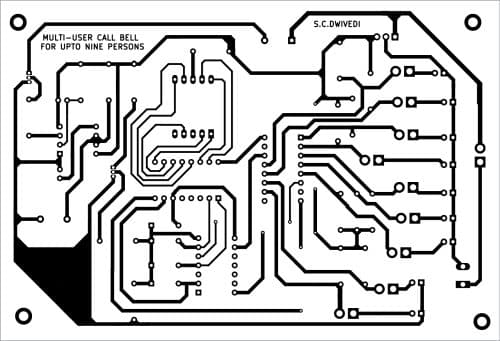
A single-side PCB layout for the call bell is shown in Fig. 3 and its component layout in Fig. 4. After assembling the circuit on PCB, enclose it in a suitable box. Install switches S1 through S9 along with their respective LEDs (LED1 through LED9) in nine different rooms or locations. The assembled PCB, including DIS1 and speaker, should be placed where the attendant is stationed.
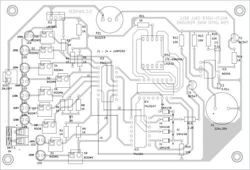
Download PCB and Component Layout PDFs: click here
S.C. Dwivedi is an electronics enthusiast and circuit designer at EFY

Can we use a push button switch for this ?
Dear Shah,
Yes, you can use a push-button switch. However, if you use a standard momentary push-button (normally open type), the circuit will remain active only while the button is pressed. As soon as you release it, the 7-segment display and buzzer will turn off. Let me know if you still have any doubts.