


 A crystal tester is an indispensable tool. Most electronics projects working with high-frequency equipment utilise crystals to generate frequency for an oscillator. Using this portable crystal tester circuit, you can test and verify the operation of a crystal between the frequencies of 1MHz and 48MHz.
Portable crystal tester circuit
Fig. 1 shows the circuit diagram of the portable crystal tester. It is built around general-purpose transistor 2N3904 (T1) and a few other components. T1 is an easily-available radio frequency (RF) transistor.
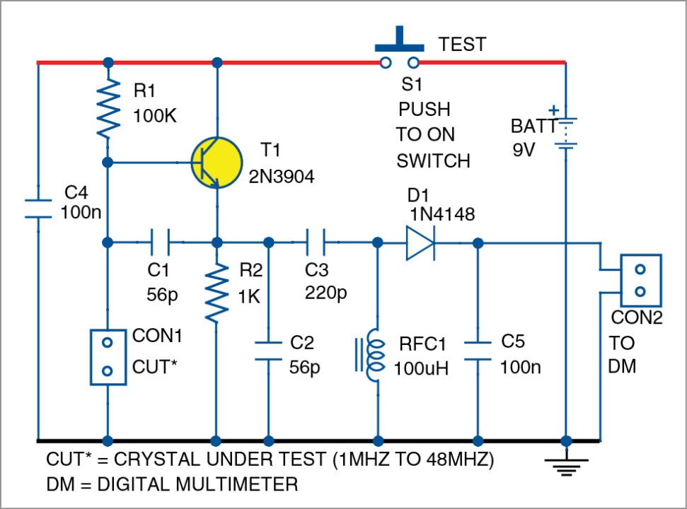
The crystal under test is connected to Colpitts oscillator comprising T1, R1, R2, C1 and C2. The oscillator has a wide frequency response, thanks to feedback capacitors C1 and C2.
Press switch S1 to test the crystal connected across CON1. If it is in working condition, T1 will start oscillating and an RF signal will be generated across RF choke RFC1. It is then converted into a DC voltage by D1 and C5. C5 charges to the peak value of the RF output.

A digital multimeter (DM) is then used to read the voltage. It can vary between 50mV and 6V for crystals that generate between 1MHz and 48MHz. Some voltage readings generated during the testing of various crystals are:
48MHz – 50mV
30MHz – 1.3V
7.6MHz – 4.2V
A digital multimeter should have a high input impedance. A faulty crystal gives a reading of 0V.
Construction and testing
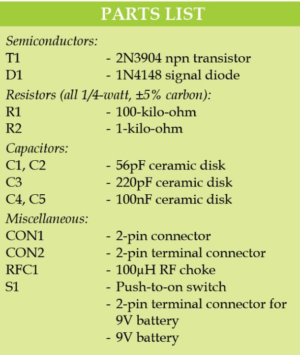
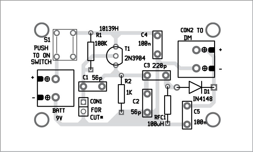
A single-side PCB for the portable crystal tester is shown in Fig. 2 and its component layout in Fig. 3.
Download PCB and Component layout PDFs: click here
Assemble the circuit on the PCB or a general-purpose PCB and house it in a small plastic box. Use a crystal socket so you can easily change the crystal. RFC1 is a 100µH ready-made RF-moulded choke. 9V battery operation is recommended for portable operation. Current consumption of the circuit is only a few milliamps.
Feel interested? Check out other electronics projects.

sir, can we test this circuit on the multisim or any other tool?
appliocation of the circuit?
Can’t this be done using breadboards?
Do we have to only use the PCB I mean do we have to fabricate the components?
excellent
What’s CON1 and CON2?
Are they any particular components or just to show that the crystals are connected there?