


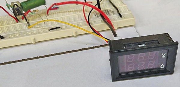
 This is a variable power supply with digital volt-amp panel meter. Its advantage is that you do not need a separate voltmeter, ammeter, or multimeter while using this variable power supply as the digital panel meter shows the voltage as well as current.
The circuit diagram of the power supply with digital VA panel meter is shown in Fig. 2.
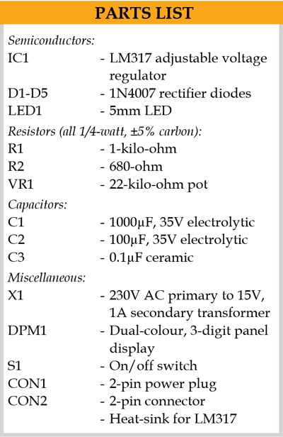
The circuit comprises LM317 adjustable voltage regulator (IC1), rectifier diodes (D1-D4), digital panel meter (DPM1), 230V AC primary to 15V, 1A secondary transformer (X1), and an LED, and a few other components.
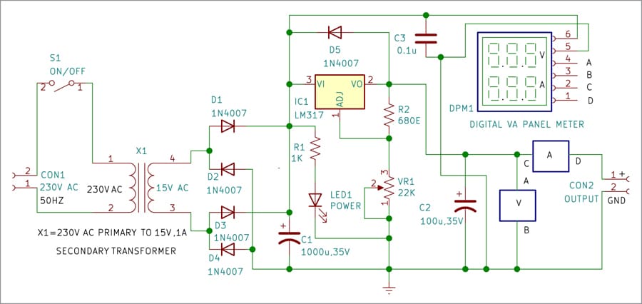
LM317 is a popular adjustable voltage regulator that comes with overvoltage protection, internal current limiting, and overload protection. So, it provides a regulated and stabilised voltage at the output, irrespective of any fluctuation in input voltage and load current. Here, the IC is designed to accept 15V as input and produce a variable DC output voltage up to 15V.
Power supply for the circuit is built around transformer X1, four diodes (D1-D4) that form a bridge rectifier, and filter capacitors C1 and C2. The secondary terminals of the transformer are connected to bridge rectifier diodes D1-D4. The glowing of LED1 indicates presence of power supply across the transformer.
Pot VR1 is connected to variable pin of the regulator IC for voltage adjustment. Capacitor C3 is used for compensating transient currents. Diode D5 connected across pins 2 and 3 of the voltage regulator gives short-circuit protection. It prevents external capacitor from discharging through the IC during an input short-circuit. The regulator maintains a constant voltage of desired level at the output. A suitable heat-sink is required for LM317 voltage regulator.
For setting a desired voltage at the output, a resistive voltage divider circuit is used between the output and ground pins of IC1. The voltage divider circuit makes use of fixed resistor R2 (680-ohm) and a pot or variable resistor (22-kilo-ohm). By selecting a correct ratio of feedback resistor (R2) and the variable resistor (VR1), the desired value of output voltage corresponding to the input voltage can be obtained. VR1 may be adjusted from its minimum to maximum position to get 0V to 15V across the load.
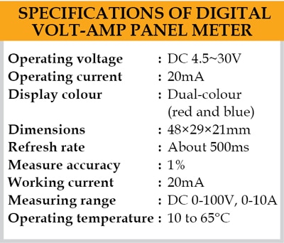
When the circuit is switched on, the digital panel meter shows 000 for voltage and 000 for current as well. The panel meter can, however, read voltage up to 100V and current up to 10A. Some important specifications of the panel meter are listed under the table.
 Construction and testing
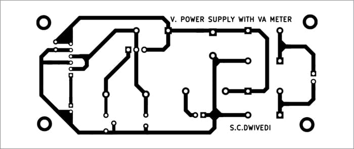
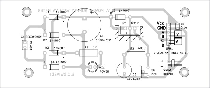
An actual-size, solder-side PCB design for the circuit is shown in Fig. 5 and its component layout is shown in Fig. 6. The circuit, being simple, can also be assembled on a breadboard or general-purpose PCB.
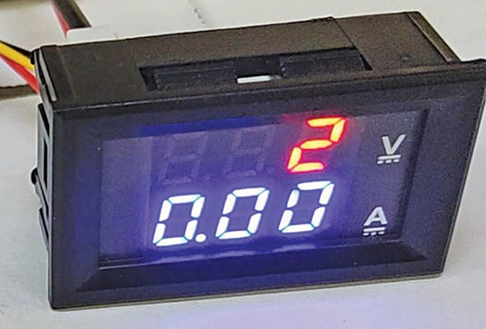
To operate, after checking that the connections have been made properly, switch on the circuit by connecting it to 230V AC mains. To measure voltage across the circuit, connect wires A and B of the panel meter to points A and B across the load (RL1). The meter will show a voltage reading, which will change as you vary VR1. Assuming that wires C and D are not connected, the reading corresponding to current will be 0.00. The 2V and 0A readings on the panel meter are shown in Fig. 3.
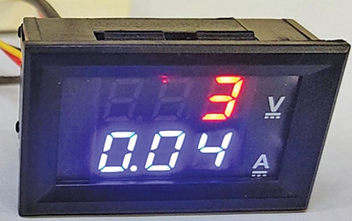
 If you want to measure current flowing through the load, connect wires C and D of the panel meter to points C and D in series with the load, as shown in the circuit. The 3V and 0.04 (or 40mA) current readings on the panel meter are shown in Fig. 4.
Depending on the power supply and the load used, you can measure current from 0 to 1.5A. However, the present circuit is designed for voltage up to 15V and current up to 1A only.
Download PCB and Component Layout PDFs: click here
Sani Theo, technical editor at EFY, is an electronics enthusiast and circuit designer
