


 Make any battery-operated toy car remote controlled using this circuit. This remote controlled toy car circuit, consisting of an infrared transmitter-receiver pair, uses IR beam transmission to switch the toy car ‘on’ or ‘off ‘. To operate the toy car, you need to hold the transmitter in your hand, keeping it pointed at the toy car which has the receiver fitted inside, and simply press a switch provided on the transmitter.
The transmitter works off 9V DC, while the receiver needs 6V DC. Fig. 1 shows the transmitter circuit. It is built around two BC558 transistors (T1 and T2), ,three BC548 transistors (T3, T4 and T5), IR LED1 and a few discrete components.
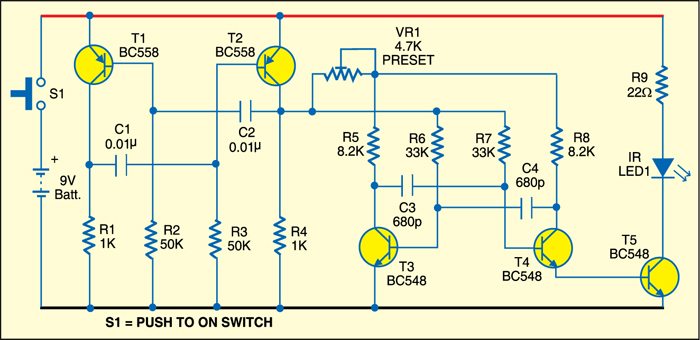
Fig. 2 shows the receiver circuit. It is built around IR receiver module TSOP1738, two BC548 transistors (T6 and T7) and a few discrete components. In the transmitter circuit, there are two astable multivibrators. The first, built around transistors T1 and T2, produces a frequency of about 1.2 kHz. The second, built around transistors T3 and T4, produces about 38 kHz. IR LED1 is used to transmit the 38kHz frequency.

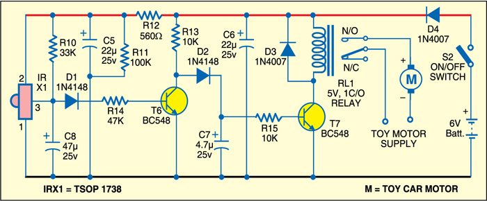
In the receiver circuit, TSOP1738 receives the IR signal transmitted by IR LED1 of the transmitter circuit. The output of TSOP1738 is fed to transistor T6 via diode D1. The amplified signal is further given to relay-driver transistor T7. Relay RL1 energises to control the toy car.
Working of the circuit is simple. Initially, when no IR beam is falling on sensor TSOP1738, the relay remains de-energised and the toy car doesn’t move. When switch S1 is pressed, the IR beam falls on TSOP1738 and its output goes low. Transistor T6 cuts off and transistor T7 conducts to energise relay RL1 and move the toy car.

Assemble both the circuits on separate PCBs. Enclose the transmitter PCB in a suitable cabinet, with IR LED1 affixed on the front side and switch S1 on the top of the cabinet. Keep the 9V battery inside the cabinet.
Enclose the receiver PCB inside the toy car, with TSOP1738 fitted such that the transmitted IR beam directly falls on it. Fix switch S2 on the body of the car and the relay inside the car. Use a 6V battery to operate the toy car receiver unit.

How much channels it have?
Where the switches are connected
Hello sir can you provide the full circuit diagram of 127mhz transmeter and receiver circuit
what kind motor do you use for the car?
thanks but assumeing i want speed,moderate,slow how do i make it
Hello Sir, may I know how the circuit works? I mean the current flows from where to where?
would be grateful if flow of current is explained in detail