


 There is huge chemical waste being generated by billions of batteries used in remote controllers for electronic devices like TV sets, set-top boxes, air-conditioners, and even some ceiling fans now-a-days. The waste produced by their spent batteries keeps increasing annually.
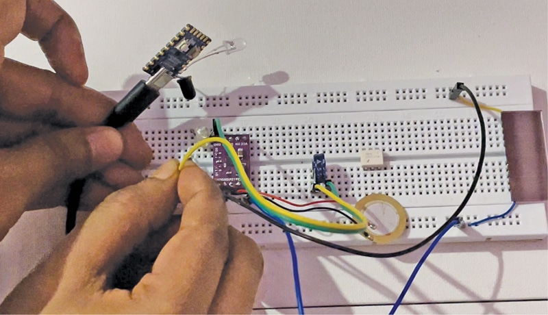
This DIY project harvests energy from the environment to power the remote controller and does not require any battery. Since low power is needed for a remote’s circuit, the battery can be eliminated altogether and thus save tons of chemical waste each year. The author’s prototype is shown in Fig. 1.

Circuit and working
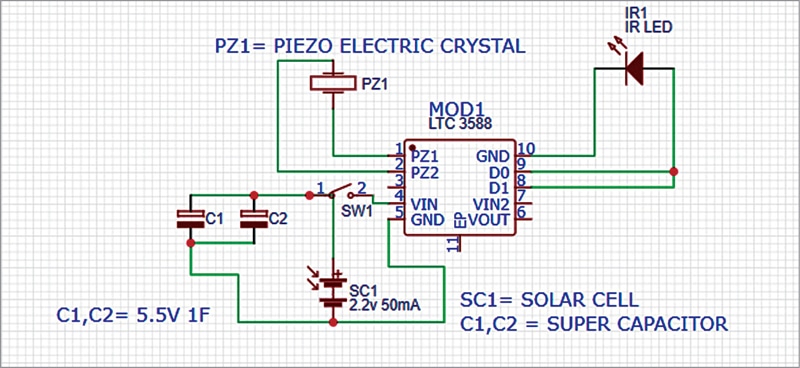
The circuit diagram of this remote controller can be divided into two sections—the transmitter and the receiver. Circuit diagram of the transmitter section is shown in Fig. 2.
The transmitter is built around energy-harvesting module LTC3588 (MOD1), two 5.5V, 1F super capacitos (C1 and C2), small 2.2V, 50mA solar cell (SC1), piezoelectric crystal (PZ1), and transmitting LED (IR1). The piezoelectric crystal is connected to input pins PZ1 and PZ2 of LTC3588. The solar cell is connected to Vin and GND pins. At the output the IR LED is connected between D0 and the ground pins of MOD1.

Circuit diagram of the receiver is shown in Fig. 3, which also includes circuit diagram of the transmitter for convenience. It is built mainly around MOD2, receiving LED/TSOP4538 (IR2), and 5mm LED (LED1). When the transmitter send the signal through IR1, it is received by IR2 in the receiver. It is necessary to ensure aligment of LED1 and LED2.
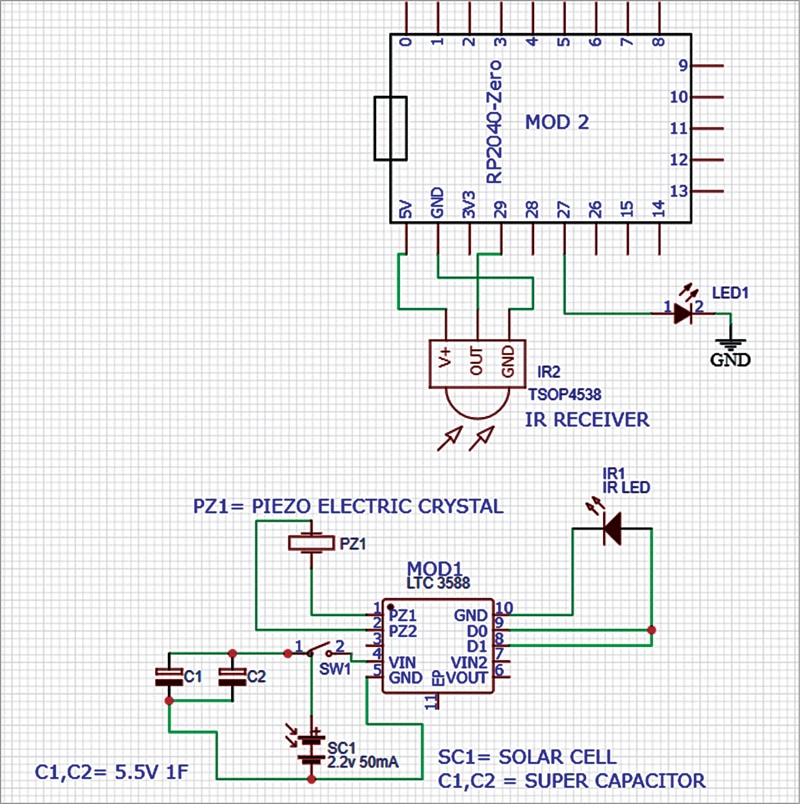
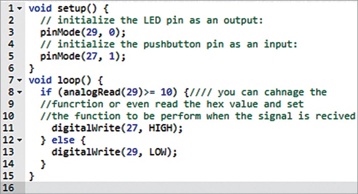
The V+, OUT, and GND pins of TSOP4538 are connected to the 5V supply, pin 29, and GND pins of MOD2, respectively. The program in source code, which is shown in Fig. 4, controls the LED. Any other function can also be included in the program for the IR signal received from the IR remote.
The components needed for this project are listed under the Bill of Material table.
mepr-show rules=”144188″ unauth=”both”]
| Bill Of Material | |||
| Component | Quantity | Description | Abbreviation |
| Solar Cell | 1 | 2.2V, 50mA | SC1 |
| Super Capacitor | 2 | 5.5V, 1F | C1, C2 |
| Piezoelectric Crystal | 1 | Piezoelectric generator | PZ1 |
| IR LED | 1 | 2.2V, 20mA | IR1 |
| Energy Harvesting Module | 1 | LTC3588 | MOD1 |
| IR Receiver | 1 | TSOP4538/IR Receiver LED | IR2 |
| RP2040 Zero Module | 1 | Microcontroller used for receiver testing | MOD2 |
| 5mm LED | 1 | LED to transmit signal | LED1 |
The beauty of this project is that the kinetic energy used for pressing a key on the remote is harvested and used to charge the capacitors. This mechanical energy is converted to electric energy by the circuit. A small solar cell is also used to harvest photonic energy from the ambient light in the room.
All of the energy harvested is stored in the super capacitors and the remote uses this stored energy to work. Thus, whenever a switch on the remote is pressed, the electric energy is used to light the IR LED and a signal is given to the receiver to perform the desired function.
Software
The operation of remote receiver circuit can be tested by using the software program, which is written in Arduino programming language Sketch and saved as batteryless.ino. The latest Arduino IDE should be used to compile and upload the program.
During uploading, you need to select the the RP2040 as board in Arduino IDE for compiling and uploading the code shown in Fig. 4.
Construction and testing
After uploading the source code batteryless.ino into MOD1 and assembling the complete circuit of transmitter and recceiver, align the circuit in such a way that IR1 light falls on IR2 (refer Fig. 3) when the piezoelectric crystal is pressed. Please ensure that the solar cell is also connected to the super capacitors to keep them charged.
Working of the circuit is simple. When the piezoelectric crystal is pressed, the generated energy makes the IR LED (IR1) glow, thus sending a signal to the receiver circuit. This signal is received by IR2 in the receiver to perform the function as per the program. Thus, the remote can work for years without any battery.
The remote can be used even in the dark, with a slight press on the piezo element.
Download source code
Ashwini Kumar Sinha is a technology enthusiast at EFY
[/mepr-show]

This article is very sketchy, explanation of the functioning is unclear. For example, how does a single piezo crystal cause the transmission of encoded signals for different functions, like “Next”, “Previous”, “Pause” etc. Most remote control have a number of buttons relating to different functions, so do we need a separate crystal for each button?
Please is there a video of how one can fully design and simulate this on MATLAB