During the testing of audio systems and telephone-like systems, it is useful to have a sinusoidal signal generator that produces forward and inverted signals in the range of around 15Hz to 15kHz. Here is one possible way of making that signal generator.
This signal generator can also be used as a sine wave oscillator, a telephone amplifier, or a low-frequency audio amplifier/driver, etc. Here we will try to make a fixed-frequency sine wave oscillator that produces four frequencies.
IC LM272 is a low-cost, easy-to-use, unity-gain, stable, dual-power operational amplifier (op-amp) that is mainly used in control applications like servo motors, power supplies, compact discs, VCRs, etc. But LM272M used in this circuit can do much more than that.

Circuit and working
Circuit diagram of the sinusoidal signal generator with forward and inverted outputs, using power amplifier LM272M, is shown in Fig. 1. Besides IC LM272M (IC1), the circuit makes use of +9V voltage regulator LM78M09 (IC2), -9V voltage regulator LM79M09 (IC3), 1N4007 rectifier diodes (D1-D8), and a few other components.
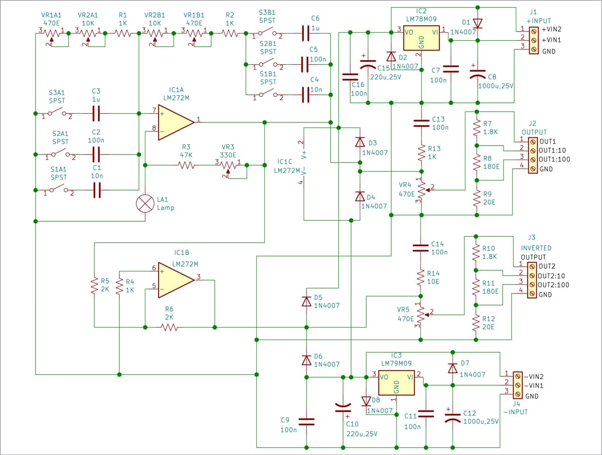
IC LM272M can produce output current up to 1A and can operate from ±2V to ±14V. Its output has low saturation voltage of around 1.5V at output current of 0.5A. The gain product bandwidth is 350kHz and the typical slew rate is 1V/µs. The typical distortion is around 0.5%. This IC has many more applications.
The circuit uses Wien bridge oscillator built around IC1A and voltage regulators 78M09 and 79M09 for producing ±9V to operate the circuit. The table on first page indicates how to select the frequencies.
| Frequencies Selection | ||||
| Range | Closed switches | Resistors using potmeters VR1 and VR2 | Capacitors | Approximate frequency |
| 1 | S1A1+S1B1 | 11.47k | 10nF | 1.4kHz |
| S1A1+S1B1 | 0.47k | 10nF | 16kHz | |
| 2 | S2A1+S2B1 | 11.47k | 100nF | 140Hz |
| S2A1+S2B1 | 0.47k | 100nF | 1.6kHz | |
| 3 | S3A1+S3B1 | 11.47k | 1µF | 14Hz |
| S3A1+S3B1 | 0.47k | 1µF | 160kHz | |
To calculate the frequency, you can use the classical formula for the Wien bridge oscillator:
F=1/(6.28×R×C)
The resistors and the capacitors should preferably have ±2% or better tolerance. The output amplitude of IC1A is set with the trimmer potmeter VR1 (VR1A1 and VR1B1). You can replace the trimmer potmeter VR1 with appropriate fixed resistors, depending on the electrical bulb LA1.
| Parts List |
|
Semiconductors:
IC1 (IC1A- IC1C) – LM272M op-amp IC2 – +9V voltage regulator, LM78M09 IC3 – -9V voltage regulator, LM79M09 D1-D8 – 1N4007 rectifier diode Resistors (all 1/4-watt, ±2% tolerance): R1, R2, R4 – 1-kilo-ohm R2 – 47-ohm R5, R6 – 2-kilo-ohm R7, R10 – 1.8-kilo-ohm R8, R11 – 180-ohm R9, R12 – 20-ohm R13, R14 – 10-ohm VR1 (VR1A1, VR1B1) – 470-ohm stereo potmeter VR2 (VR2A1, VR2B1) – 10-kilo-ohm stereo potmeter VR3 – 330-ohm potmeter VR4-VR5 – 470-ohm potmeter Capacitors (preferably with 2% or less tolerance): C1, C4 – 10nF ceramic disc C2, C5, C7, C9, C11, C13, C14, C16 – 100nF ceramic disc C3, C6 – 1µF polyester C8, C12 – 1000µF, 25V electrolytic C10, C15 – 220µF, 25V electrolytic Miscellaneous: S1 (S1A1, S1B1), S2 (S2A1, S2B1), S3 (S3A1, S3B1) – Stereo on/off switch LA1 – 6V, 20mA/6V, 40mA/12V, 20mA J1, J4 – 3-pin terminal connector J2, J3 – 4-pin terminal connector – Heat-sink for TO220 package (2 pcs) |
The circuit works with ±12V regulated power supply. The +12V supply is given to +VIN1 terminal and the -12V supply to -VIN1 terminal. In place of +12V and -12V, you can connect +9V and -9V across +VIN2 and -VIN2, respectively, if ±12V is not available. The circuit can work with up to ±14V, but it is suggested to keep the power supply of the IC around ±9V, because the IC can overheat if it is loaded with high current.
The circuit has two outputs, one of which is normal and available across terminal J2, and the other is inverted and available across terminal J3. The first output OUT1 gives a signal with frequencies produced from the first oscillator IC1A. The amplitude of these outputs is adjusted with potmeter VR4. OUT1:10 is divided by 10 of OUT1, while OUT1:100 is divided by 100 of OUT1.
The inverted output gives signal with frequencies produced from IC1B across terminal J3. The output OUT2 is also produced from the first oscillator IC1A, but it is inverted. The amplitude of these outputs is adjusted with potmeter VR5. OUT2:10 is divided by 10 of OUT2, while OUT2:100 is divided by 100 of OUT2.
The snubber circuits at the outputs of op-amps are not obligatory. But in case of need, we can connect in series a resistor of 1- to 3-ohm and capacitors of 47 to 220nF with each op-amp, depending on expected loads. To stabilise the amplitude of IC1A, we may use lamps rated at 6V/20mA, 6V/40mA, 12V/20mA, etc.
The circuit can be used at home, in a lab, or in the field, because it can work from battery (2×4.5V, 2×6V, or 2×9V). It needs a simple adjustment of the amplitude of the oscillator built around IC1A to work properly.
Construction and testing
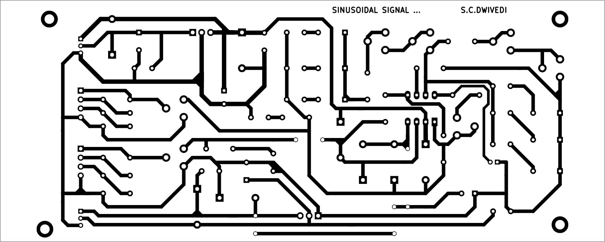
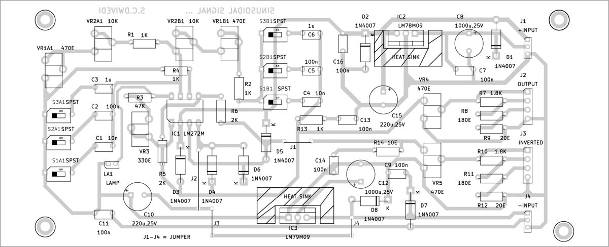
A single-side PCB for the sinusoidal signal general is shown in Fig. 2 and its component layout in Fig. 3. After assembling the circuit on a PCB, connect the power supply across terminals J1 and J4 in the PCB. Fix potmeters VR1 through VR5 on the front side of the cabinet so that you can adjust them to get the required frequencies.
EFY Notes. 1. The simultaneous adjustment of the output voltages can be made with a stereo potentiometer for VR1 (VR1A1, VR1B1) and VR2 (VR2A1, VR2B1)
-
The output voltages can be adjusted more precisely with individual potentiometers, say, VR4 and VR5.
Download PCB and Component Layout PDFs: click here
Petre Tzv Petrov was a researcher and assistant professor at the Technical University of Sofia, Bulgaria, and expert lecturer in OFPPT (Casablanca), Kingdom of Morocco. Currently, he is working as an electronics engineer in the private sector in Bulgaria