


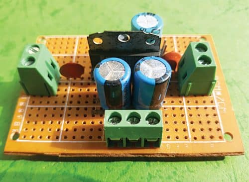
 Here is a simple stereo audio amplifier that can be made using a TDA1517 IC. A 14.4V regulated voltage is used as power supply for this amplifier. TDA1517 is a 9-pin (single-in-line package) audio amplifier IC, which is inexpensive and easily available online. The author’s prototype is shown in Fig. 1.
Circuit and working
The circuit diagram of the stereo AF amplifier is shown in Fig. 2. Its left channel audio input is connected to pin 1 of IC1 through VR1 (10k) potmeter and capacitor C1 (220nF). The right channel audio is connected to pin 9 through VR2 (10k) potmeter and capacitor C2 (220nF).
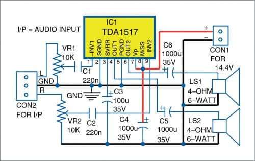
Pins 2 and 5 of IC1 are connected to the ground. The left channel audio output is available at pin 4 of IC1, which is connected to the left speaker (LS2) through capacitor C5 (1000µF, 35V). The right channel output is available at pin 6, which is connected to the right speaker (LS1) through capacitor C6 (1000µF, 35V). Pins 7 and 8 are connected to the +14.4V power supply.

Construction and testing
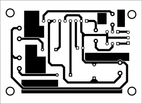
You can assemble the circuit on a 5cm×7cm veroboard or on a PCB whose actual-size layout is shown in Fig. 3 and the components layout in Fig. 4. After assembling the circuit on the PCB, connect the 14.4V regulated power supply across CON1.

Download PCB and Component layout PDFs: click here
First, mount TDA1517 IC on the veroboard or PCB. Now place two 2-pin terminal connectors on the PCB for left and right speakers. Then mount all the ceramic and electrolytic capacitors as per the circuit. Take a 15-watt soldering iron and solder all the components on the board. Place a 3-pin connector on the board for audio input connections.
You may also use an IC socket. For that, take an 18-pin IC socket, cut it into half, and use only one side (9-pin) for TDA1517. Solder the 9-pin IC socket on the PCB. Using an IC socket avoids direct heating of the actual IC and reduces heat and damage to the IC during soldering.
Use a suitable heat-sink for the IC. You can make a heat-sink using a suitable piece of aluminium. Measure the distance between the two holes provided on the fin of TDA1517 for mounting the heat-sink. Then make two holes (3mm each) for the screws/bolts on the aluminium, using an electric drill machine, at the exact distance of holes on the fin. Fix the home-built aluminium heat-sink on the fin with screws.
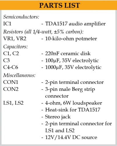
Calibration
You will need a signal generator for calibration and adjustment in the prototype. Take a 12V battery and connect it to your prototype. Connect a 4-ohm, 6W speaker each to LS1 and LS2, respectively, as shown in Fig. 2.
Now slowly increase the volume control (VR1) after connecting the signal generator (with 1kH signal) to the left input. You’ll hear sound coming from LS1 speaker. Similarly, connect the signal generator to the right input and slowly increase the volume control (VR2) to hear sound from LS2 speaker.
If you do not have a signal generator, use a metal screwdriver for testing your prototype. Gently touch the screwdriver on the right and left inputs of your prototype. You will hear a humming sound from the right and left speakers.
Finally, connect a stereo jack to the input (CON2) of your amplifier. Then feed an audio signal to CON2 from an audio source such as an MP3 player or a computer. Adjust VR1 and VR2 to middle positions. You’ll hear clean audio output from the speakers (LS1 and LS2).
Raj K. Gorkhali is an electronics hobbyist and a regular contributor to EFY