In this project, an ultrasonic detector is mounted on top of a tank for the detection of liquid level. Monitoring the liquid level in tanks and vessels is one of the most important parameters in process industries.
In process plants, tanks contain various liquids that are often quite expensive. Some of the liquids are inflammable and corrosive as well. Hence, it is better to monitor and control the level of liquid in tanks so that it does not overflow.
The ultrasonic level detector proposed here is a popular non-contact type level detector. It operates by generating an ultrasonic pulse and measuring the time it takes for an echo to return. The travelling time indicates the depth of the empty space above the liquid in the tank. If the detector is mounted on top of the tank, the pulse travels in air at a speed of 331m/sec at 0°C.
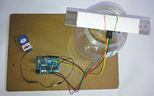
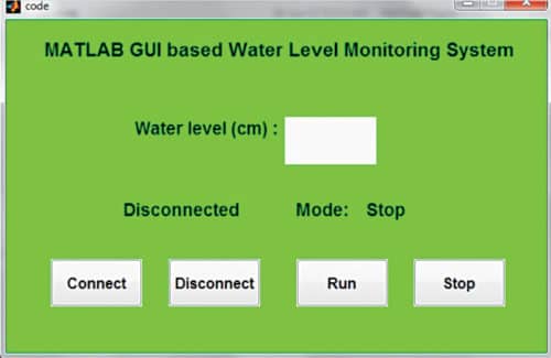
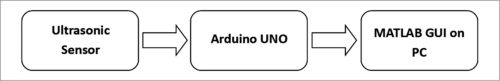
The authors’ prototype is shown in Fig. 1. A screenshot of MATLAB based GUI used for level monitoring is shown in Fig. 2. The block diagram of the project is shown in Fig. 3.
Fig. 1: Authors’ prototype of the Ultrasonic Liquid Level Monitoring System projectFig. 2: Screenshot of MATLAB based GUIFig. 3: Block diagram of the Ultrasonic Liquid Level Monitoring System project
Circuit and working
The major components used in this project are:
Arduino Uno
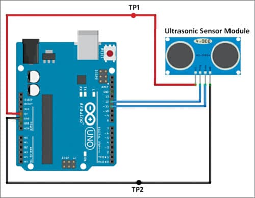
Arduino Uno is an AVR ATmega328P microcontroller based development board with six analogue input pins and 14 digital I/O pins. The microcontroller has 32kB ISP flash memory, 2kB RAM, and 1kB EEPROM. The board provides the capability of serial communication via UART, SPI, and I2C. The microcontroller can operate at a clock frequency of 16MHz. In our project, digital I/O pins 11 and 12 of Arduino are connected to echo and trigger pins of the ultrasonic sensor module, respectively.
Ultrasonic ranging module HC-SR04 provides excellent non-contact range detection from 2cm to 400cm, with an accuracy of up to 3mm. The module includes an ultrasonic transmitter, receiver, and control circuit. The module used here has four pins—echo, trigger, Vcc, and GND. The basic principle of operation of the module is as follows:
Trigger pin is an input pin. It is made for a high pulse of at least 10µs duration, on receipt of which it automatically sends eight sonic bursts of 40kHz (ultrasonic signals). This signal, after reflecting from the object, is received by the echo pin.
The echo pin is an output pin that goes high for a period of time that is equal to the time taken for the ultrasonic wave to return to the sensor. The echo pin provides the travelling time of the sound wave in microseconds.
The connections diagram for the project is shown in Fig. 4.
Fig. 4: Connections diagram for the Ultrasonic Liquid Level Monitoring System project
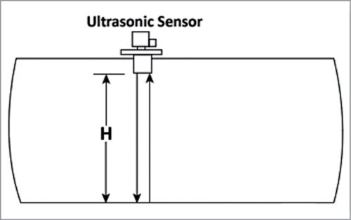
The ultrasonic sensor measures the distance between the sensor and object/liquid by sending an ultrasonic wave and calculating the time required for the echo to return. If the time between the trigger and echo is known, the distance of the object can be calculated by simply multiplying half of the time with the speed of sound in air. This principle is used here to detect the level of liquid in a tank. The working of the sensor is illustrated in Figs 5 and 6.
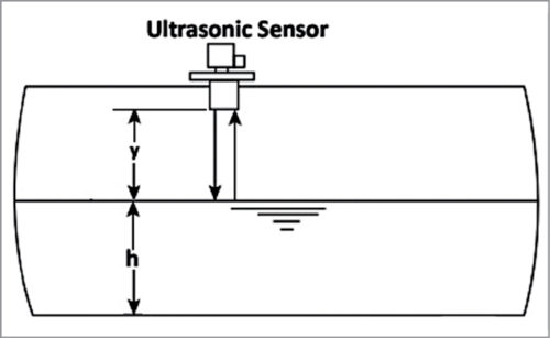
Fig. 5: Empty tankFig. 6: Tank filled with liquid
As shown in Fig. 5, when the tank is empty, the ultrasonic wave hits the bottom of the tank and gets reflected. As a result, it detects the depth of the empty tank at ‘H’ height. If the tank is filled with liquid up to ‘h’ height, the ultrasonic wave is reflected from the liquid’s top surface, and it detects the depth of empty space ‘y’ above the liquid, as shown in Fig. 6. When ‘H’ and ‘y’ are known, the liquid level ‘h’ can be calculated by subtracting ‘y’ from ‘H,’ that is, h=(H-y). The value of H is calculated only once during the initial calibration when the tank is empty. For our setup, the value of H was 17cm.
Software
The GUI application program has been developed in the R2014a version of MATLAB. For the Arduino code, the ‘NewPing’ library has been used. The steps for programming Arduino board are:
Open Arduino IDE.
Go to Sketch->Include Library->Add .ZIP Library.
Browse and select NewPing_v1.7. (The library is provided with the source code.)
Connect the Arduino board and select the proper board and COM port from the Tools menu.
Upload the code ‘Arduino_code.ino’ to the board.
The MATLAB code consists of files ‘code.m’ and ‘code.fig’. Keep both the files in the same folder. Open the file ‘code.m.’ Find the line s=serial(‘COM9’) (on line no. 88), and replace ‘COM9’ with COM port on which your Arduino board is installed.
Run the file ‘code.m.’ After running this file, GUI will appear, as shown in Fig. 2. Click on the ‘Connect’ button to connect Arduino with MATLAB. Click on the ‘Run’ button to monitor the level of liquid. Click on the ‘Stop’ button to stop monitoring. To disconnect MATLAB and Arduino, click on the ‘Disconnect’ button.
Make the connections as shown in Fig. 4. Place the ultrasonic sensor at top of the tank.
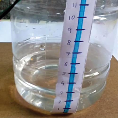
You can test the project using a suitable plastic water container. The ultrasonic module can be fixed on top of the container, as shown in Fig. 1. If the reading shows 0, it means the tank is empty. When the water level rises, readings will also keep increasing. If the reading shows that the water is up to the maximum level, it’s time to close the water inlet of the tank (or stop the water pump).
Fig. 7: Calibrated water container
The voltage levels at different test points in the connections diagram are shown in the test point table.
Also Check:
Saikat Patra is passionate about electronics and MCU based embedded system applicationsShibendu Mahata is M.Tech in Instrumentation and Electronics Engineering from Jadavpur University. He loves designing MCU based real-time embedded signal processing and process control systems
Shibendu Mahata is M.Tech (gold medalist) in instrumentation and electronics engineering from Jadavpur University. He has contributed over 20 papers in the domain of signal processing in reputed international journals, conferences, and book chapters.
5 COMMENTS
How the Program will be install in the Aurdino; we required the software
First, download Arduino IDE from the link https://www.arduino.cc/en/software. Install it in your system. Download the code from the Arduino source code link given in the article above. Run Arduino IDE, open Arduino_code.ino, compile/verify it and upload it to Arduino board.


 In this project, an ultrasonic detector is mounted on top of a tank for the detection of liquid level. Monitoring the liquid level in tanks and vessels is one of the most important parameters in process industries.
In process plants, tanks contain various liquids that are often quite expensive. Some of the liquids are inflammable and corrosive as well. Hence, it is better to monitor and control the level of liquid in tanks so that it does not overflow.
The ultrasonic level detector proposed here is a popular non-contact type level detector. It operates by generating an ultrasonic pulse and measuring the time it takes for an echo to return. The travelling time indicates the depth of the empty space above the liquid in the tank. If the detector is mounted on top of the tank, the pulse travels in air at a speed of 331m/sec at 0°C.
The authors’ prototype is shown in Fig. 1. A screenshot of MATLAB based GUI used for level monitoring is shown in Fig. 2. The block diagram of the project is shown in Fig. 3.
In this project, an ultrasonic detector is mounted on top of a tank for the detection of liquid level. Monitoring the liquid level in tanks and vessels is one of the most important parameters in process industries.
In process plants, tanks contain various liquids that are often quite expensive. Some of the liquids are inflammable and corrosive as well. Hence, it is better to monitor and control the level of liquid in tanks so that it does not overflow.
The ultrasonic level detector proposed here is a popular non-contact type level detector. It operates by generating an ultrasonic pulse and measuring the time it takes for an echo to return. The travelling time indicates the depth of the empty space above the liquid in the tank. If the detector is mounted on top of the tank, the pulse travels in air at a speed of 331m/sec at 0°C.
The authors’ prototype is shown in Fig. 1. A screenshot of MATLAB based GUI used for level monitoring is shown in Fig. 2. The block diagram of the project is shown in Fig. 3.
How the Program will be install in the Aurdino; we required the software
First, download Arduino IDE from the link https://www.arduino.cc/en/software. Install it in your system. Download the code from the Arduino source code link given in the article above. Run Arduino IDE, open Arduino_code.ino, compile/verify it and upload it to Arduino board.
while trying to connect arduino with matlab .matlab shows like… Error while evaluating UIControl Callback.How can i rectify this
when i try to connect matlab with arduino its show error like…(error while call back UI control) how can i rectify this
May be your are using another MATLAB version. You may try R2104a and see if its giving same error