LEDs are one of today’s most energy-efficient and rapidly advancing lighting technologies. However, High intensity discharge (HID) lamps are still an attractive lighting choice in recent times for their many advantages over incandescent and fluorescent lighting. Some of the benefits include long life, high luminous efficacy (lumens/watt), among others. HID lamps have found their way into lighting for ceiling, streets, airports, stadiums, and even automotive headlights.
HID lamps need a circuit to control the current flowing through them, often called a ballast. This circuit must limit the lamp current to a safe maximum value to prevent its destruction. Traditional ballasts come with many disadvantages such as low power factor, bulky capacitors and large size. Emerging trend to drive HID lamps is towards electronic ballasts which are becoming more and more efficient.
If you are curious to design your own efficient electronic ballast for a HID lamp, here are a few industry-standard reference designs put together along with all supporting documents:-

Electronic Ballast for 250W HID Metal Halide Lamp:
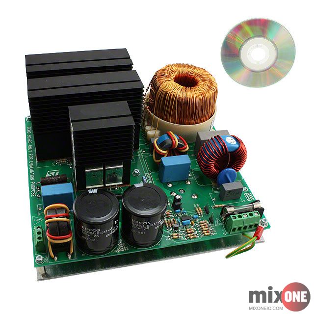
This reference design describes an electronic ballast for a 250 W HID metal halide lamp. The ballast is composed of a boost converter and an inverter. The boost converter regulates the output voltage and performs the power factor correction. The inverter stage is composed of a full bridge that converts the DC current coming from the PFC stage into an AC current for the lamp. The inverter drives the lamp at low frequency square wave. The design utilizes an ST7LITE3 microcontroller from STMicroelectronics. More on this Reference Design
Automotive Headlamp HID Ballast:
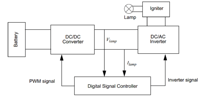
This reference design discusses an automotive HID electronic ballast using a 16-bit GS series Digital signal controller (DSC) from Microchip. The ballast in this reference design consists of four sections: High frequency DC/DC converter, Low frequency DC/AC inverter, ignition circuit and a Digital Signal Controller. The dsPIC DSC detects the lamp voltage and lamp current through the Analog-to-Digital Converter (ADC), and adjusts the PWM duty cycle of the DC/DC converter to control the lamp current. Meanwhile, several fault signals are monitored by the digital signal controller. Open circuit protection and short circuit protection are implemented by the internal comparators of the dsPIC. The DSC measures the battery voltage through the ADC. If the battery voltage is outside the normal operation range, the ballast will stop working. More on this Reference Design
Driver for 70W HID Lamp:
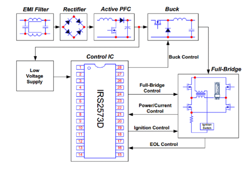
Here is a complete ballast solution for a 70W HID lamp. The design contains an EMI filter, low voltage power supply, active power factor correction and a ballast control circuit using the IRS2573D ballast control IC from International Rectifier. The ballast IC IRS2573D is fully integrated with advanced control features such as ignition timing control, constant lamp power control, current limitation control, programmable full-bridge running frequency, programmable over and under-voltage protection and open load and short circuit protection. More on this Reference Design
Dimmable Dual Lamp HID ballast:
This reference design discusses a dimmable electronic ballast for two T5 35 W lamp types in parallel. Based on UBA2015AT ballast controller IC from NXP, the design works on 230V mains supply. The design features a programmed start with preheat with starting time less than one second. The reference design comes equipped with complete documentation. More on this Reference Design