


For most of the time having a real conversion with a computer has seemed something that was really far away, until now. Alexa voice service (AVS) is one such technology which helps to achieve this goal with IOT of flexibility. Extending this flexibility to a step further to home automation using speech commands to provide a more interactive and user friendly living experience.
This project presents the design of the voice recognition based home automation system for differently abled people, geriatrics and many more to control the various home appliances.
Our focus is on making non-smart homes into smart and to build a robust, cost-effective system that can be widely used.

Introduction
Automation is frequently spelled in the field of electronics. The hunger for automation brought many changes in the present technologies. This has a greater importance than any other technologies due to its user-friendly nature.
An essential part in Automation is Home automation. Home automation means the monitoring, and control of household electronic devices intelligently for effective usages. The household objects should be intelligently interconnected as well as provide information for better operations. Home automation interfaced with the Internet of Things (IoT) provides greater flexibility in controlling household objects in a wider aspect. This will support inter connectivity of numerous smart homes for a better resource utilization in wider area.
This can be achieved using many technologies present right now. To achieve this in a simpler way Amazon Echo is used which is a voice-enabled wireless speaker developed by Amazon. The device connects to the voice controlled personal assistant service Alexa, which responds to the word or name, “Alexa.” The device is capable of voice interaction, play music, making to-do lists, sets alarm, streaming podcasts, and providing weather, traffic, and other real time information. It can also control several smart devices using different skills present in it.
To control smart devices using Alexa is very simple, but altering non-smart devices to smart devices are not affordable by everyone. So, the objective of our product is to provide a cheap and inexpensive way to control non-smart devices using the power of voice.
Amazon Echo is a smart speaker that has been developed by the Amazon Company that can be used to control a lot of smart devices. We use the Amazon Echo to develop a skill that will communicate with our circuit to control our devices.
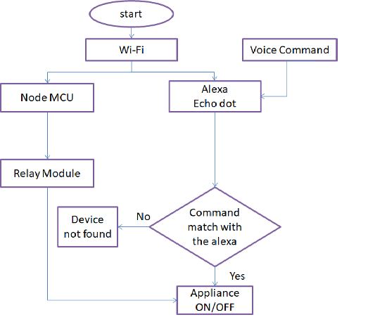
The controller for the automation in this project is NodeMcu. The command is given by the user to Alexa and then NodeMcu read the data through Wi-Fi and decides the switching action of electrical devices connected to it through Relays where it acts as fuse.
Circuit and Working
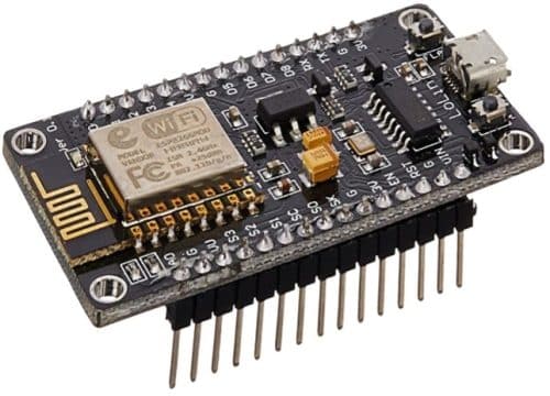
1. NODEMCU: NodeMCU is a low-cost open source IoT platform. It initially included firmware which runs on the ESP8266 Wi-Fi SoC from Espressif Systems, and hardware which was based on the ESP-12 module and support for the ESP32 32-bit MCU was added later. Both the firmware and prototyping board designs are open source.
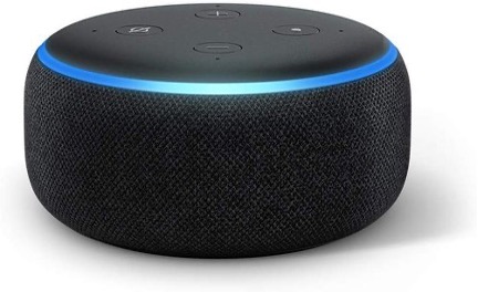
2. AMAZON ECHO DOT: Amazon Echo (shortened to Echo) is a brand of smart speakers developed by Amazon. Echo devices connect to the voice-controlled intelligent personal assistant service Alexa, which will respond when you say “Alexa”.
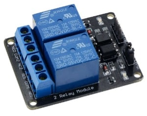
3. REALY MODULE: The Relay module is a separated hardware device used for remote device switching. With it you can remotely control devices over a network or the internet. Devices can be remotely powered on or off with commands coming from Clock Watch Enterprise delivered over a local or wide area network. You can control computers, peripherals or other powered devices from across the office or across the world.
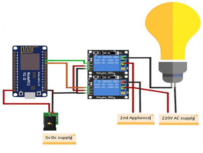
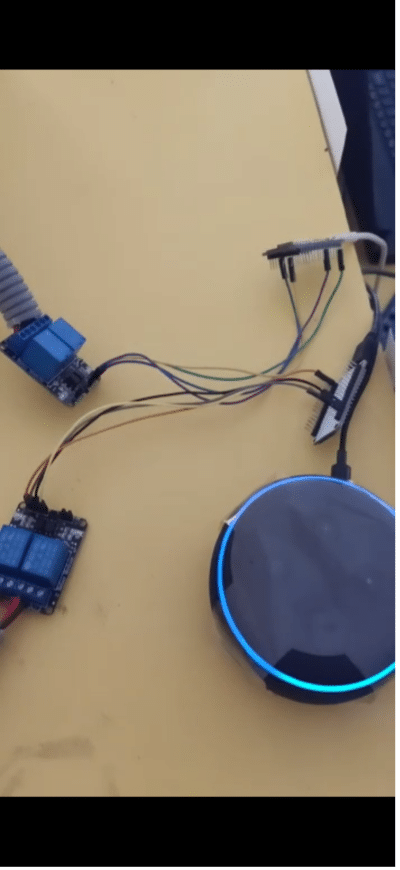
Connect all the components as shown in the above circuit diagram. The input pins IN1, IN2 of the 2 channel relay are connected to digital pins of the NodeMCU. Connect to the pins according to the code. The ground pin in NodeMCU and the relay are connected similarly; the Vcc pin of relay is connected to Vin of NodeMCU. Vcc and GND pins of NodeMCU are connected to external 5v DC Supply. One terminal of the appliance is connected directly to the relay (normally open) and the other is in series with 220V AC Supply and the relay pin (common).
Software
Flow Chart:
The software used for this project is Arduino for the microcontroller and Sinric from Alexa app to interface with hardware.
Install the Arduino software and install the necessary boards required for NodeMCU as shown in the below figure.
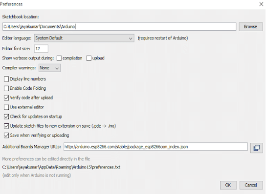
- Copy the link in the Additional boards Manager
- Click OK to close the preference Tab.
- After completing the above steps, go to Tools and board, and then select board Manager
- Navigate to esp8266 by esp8266 community and install the software for Arduino.
- Once all the above process been completed we are ready to program our NodeMCU with Arduino IDE.
Sinric
Install Alexa app in your Android or iOS and complete the setup of Amazon Alexa. Next, Open chrome or Firefox and copy the link www.sinric.com which appears like the figure below.
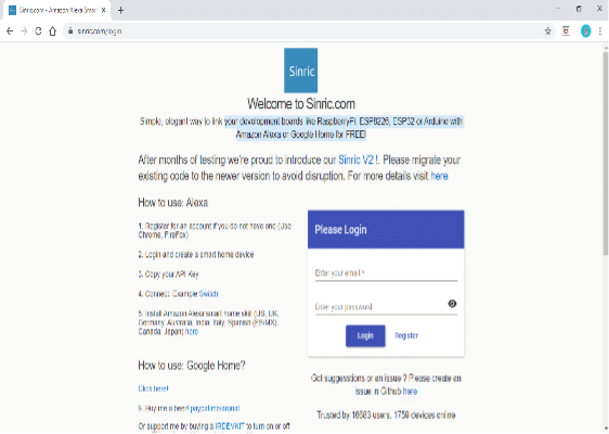
Click on register and register for a free account and login into your account. There you can find your API key which is unique and options to generate smart home devices
Construction and Testing
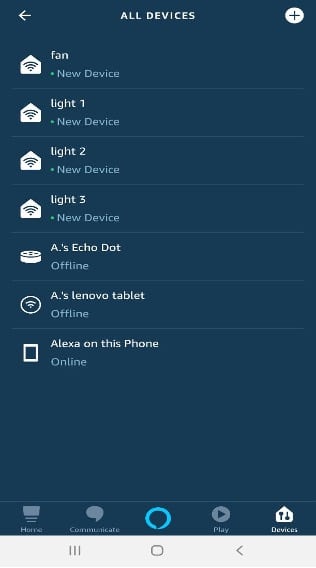
Interface the NodeMCU and the Alexa. Now start discovering the devices by saying “Alexa discover devices”. After discovering the devices, the discovered devices are displayed in the app as shown in Fig. 7
Note that the wifi ssid and password for NodeMCU and wifi to which Alexa is connected should be same.
Now, we can send commands to Amazon Echo:
Alexa will respond to the following commands:
“Alexa, turn on light 1”
“Alexa, turn off light 1”
“Alexa, turn on light 2”
“Alexa, turn on light 2”
“Alexa, turn on light 3”
“Alexa, turn off light 3”
“Alexa, turn on fan”
“Alexa, turn off fan”
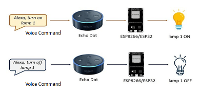
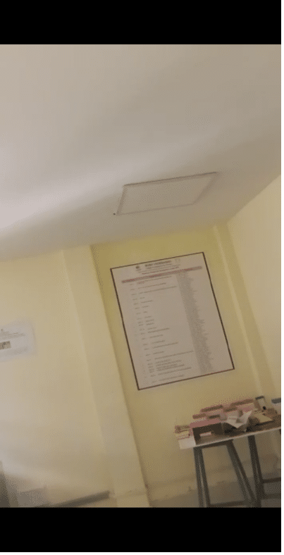
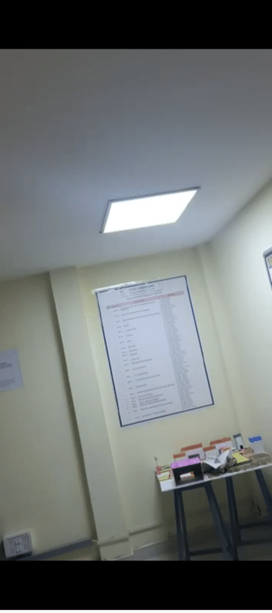
When we say something like “Alexa, turn on light 1”, the ESP8266 will trigger a relay to turn on light 1. When you say something like “Alexa, turn off light 1”, the ESP8266 will send a signal to the relay to turn off the light1. This works similarly for light2, light3 and fan as shown in Fig. 8
Source Code
#include // arduino hearder file
#include // header file for ESP8266
#include “fauxmoESP.h” // hearder file for fauxmoESP
#define WIFI_SSID “xxxx” // replace xxxx with your Wi-Fi SSID
#define WIFI_PASS “xxxx” // replace xxxx with the password
#define SERIAL_BAUDRATE 115200
#define l D2
#define r D3
fauxmoESP fauxmo;
void wifiSetup() {
WiFi.mode(WIFI_STA);
Serial.printf(“[WIFI] Connecting to %s “, WIFI_SSID);
WiFi.begin(WIFI_SSID, WIFI_PASS);
while (WiFi.status() != WL_CONNECTED) {
Serial.print(“.”);
delay(100);
}
Serial.println();
Serial.printf(“[WIFI] STATION Mode, SSID: %s, IP address: %s\n”, WiFi.SSID().c_str(),
WiFi.localIP().toString().c_str());
}
void setup() {
pinMode(l, OUTPUT);
pinMode(r, OUTPUT);
Serial.begin(SERIAL_BAUDRATE);
Serial.println(“FauxMo demo sketch”);
Serial.println(“After connection, ask Alexa/Echo to ‘turn on’ or ‘off'”);
wifiSetup();
fauxmo.addDevice(“light 1”);
fauxmo.addDevice(“fan”);
// Gen3 Devices or above port number will be used
fauxmo.setPort(80);
fauxmo.enable(true);
fauxmo.onSetState([](unsigned char device_id, const char * device_name, bool state, unsigned char value) {
Serial.print(“Device: “); Serial.print(device_name);
Serial.print(” state”);
if (state) {
Serial.println(“ON!”);
}
else {
Serial.println(“off”);
}
if ( (strcmp(device_name, “light 1”) == 0) )
{
if (state)
{
digitalWrite(l, LOW);
}
else
{
digitalWrite(l, HIGH);
}
}
if ( (strcmp(device_name, “fan”) == 0) )
{
if (state)
{
digitalWrite(r, LOW);
}
else
{
digitalWrite(r, HIGH);
}
}
});
}
void loop() {
fauxmo.handle();
}
Authors:
N. M. Sai Krishna, Assistant Professor at BVRIT Hyderabad.
R. Priyakanth, Associate Professor at BVRIT Hyderabad.
A. Pranava, Final year student from BVRIT Hyderabad.
D. Sri Devi, Final year student from BVRIT.
P. Jahnavi Akhila, Final year student from BVRIT Hyderabad.
M.Aanjalaa, Final year student from BVRIT Hyderabad.
Thanks to you all N. M. Sai Krishna, R. Priyakanth, A. Pranava, F, D. Sri Devi, P. Jahnavi Akhila, and M. Aanjalaa. You really have put so much effort in creating this article. Thankyou for this comprehensive article.