The circuit presented here is a simple device to enhance the utilisation of hot water from a solar water heater system. Normally, during day time, you get hot water continuously from the solar water heater due to the presence of sunlight. But in absence of sunlight, freshwater keeps getting added to the tank and cools the water, which is not desirable, especially in winter. This is not a good way of utilising hot water at home.
By controlling cold water at the tank inlet in the absence of sunlight, we can utilise the available hot water in a better way. This circuit is specially designed to fulfil this requirement and can be installed in the existing solar water heater by making some minor changes.
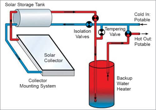
The typical block diagram of the solar water heater system is shown in Fig. 1. Hot water gets circulated through a solar collector, which collects heat by absorbing sunlight. This water is then stored in a storage tank, or piped into an additional backup water heater tank. We are going to add a solenoid valve at cold water inlet in such a solar water heater system.

Circuit and working
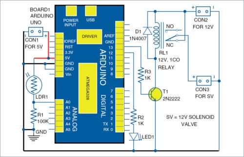
The circuit diagram of the hot water utilisation enhancer is shown in Fig. 2. It consists of Arduino Uno (Board1), LDR1 (light dependent resistor), 12V single changeover (1CO) relay, 12V solenoid valve, and a few other components. The circuit diagram of the power supply is shown in Fig. 3.
Arduino Uno
Arduino Uno board is connected to LDR1, indicator LED1, and relay RL1. The light intensity read by LDR1 is recorded and processed by the Arduino Uno board, which further commands the relay according to the program’s condition.
Power supply
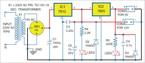
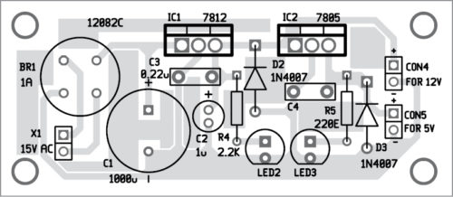
The power supply is used to power a 12V solenoid valve and relay (RL1) for switching. 5V DC is also derived from this power supply. It consists of a 230V primary to 15V AC, 1A secondary transformer (X1). The output of this step-down transformer is given to full-bridge rectifier BR1 and two capacitors of value 1000µF, 35V (C1), and 1µF, 25V (C2). 12V regulator 7812 (IC1) and 5V regulator 7805 (IC2) are used for providing 12V and 5V regulated power supplies, respectively. Diodes D2 and D3 are provided to prevent reverse polarity during connections. LED2 is a 12V DC indicator, and LED3 is a 5V DC indicator.
Light-dependent resistor
It is connected to analogue pin A0 of the Arduino board. LDR1 is used as a light detector. The resistance of LDR1 decreases with the increase in light intensity bombarded on it. In absence of light, the resistance of LDR1 may reach up to a few mega-ohms (M), while in the presence of light, its resistance reduces to a few ohms (). The reduction in its internal resistance increases conductivity.
Relay
Relay RL1 is an electromagnetic switching device, which provides complete electrical isolation between the controlling circuit and output circuit. It is controlled/triggered by a low DC. A 12V single-changeover relay is used here to switch the solenoid valve on and off with the use of an electrical pulse.
Solenoid valve
Solenoid valve (SV) is an electrically operated valve. Basically, there are two types of solenoid valves according to the operation state: normally open (NO) and normally closed (NC). These valves are used to control the flow of fluid. If the flow of fluid is stopped when the solenoid valve is energised, it is a normally open (NO) solenoid valve. If the flow of fluid is stopped when the solenoid is de-energised, it is a normally closed (NC) solenoid valve. Here, a 12V DC NC solenoid valve is used. The water flows when the solenoid is energised.
Software
Arduino program (Utilization_enhancer.ino) is used for this prototype. This program code must be uploaded to Arduino Uno using Arduino IDE. In the program, digital pin 13 of the Arduino board is defined as the output. Its analogue pin A0 is used to read analogue input signals. Some main functions of the Arduino code are explained below:
pinMode()
It configures the specified pin to behave either as an input or output. See the description of digital pins for the functionality of the pins.
DigitalWrite()
If any Arduino pin is configured as output with pinMode(), its voltage will be set to corresponding values: 5V (or 3.3V on 3.3V board) for high and 0V (ground) for low.
Serial. It is used for communication between the Arduino board and computer or other devices. All Arduino boards have at least one serial port (also known as UART or USART).
Begin()
It sets the data rate in bits per second (baud) for serial data transmission. For communicating with the computer, use one of these rates: 300, 600, 1200, 2400, 4800, 9600, 14400, 19200, 28800, 38400, 57600, or 115200. You can, however, specify other rates—for example, you can communicate over pins 0 and 1 with a component that requires a particular baud rate.
AnalogRead()
It reads the value from the specified analogue pin. The Arduino board contains a multichannel, 10-bit analogue-to-digital converter. This means that it will map input voltages between 0 and operating voltage (5V or 3.3V) into integer values between 0 and 1023.
println()
It prints data on the serial port as human-readable ASCII text followed by a carriage return character.
Delay()
It is used to pause the program for the amount of time (in milliseconds) specified as a parameter.
Construction and testing
First, assemble the power supply circuit. An actual-size PCB layout for the power supply section is shown in Fig. 4 and its components layout in Fig. 5. After assembling the circuit on the PCB, connect it with the Arduino Uno board, relay, and solenoid valve as shown in Fig. 1 via jumper/external wires.
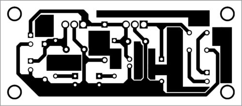
Download PCB and Component Layout PDFs: click here
Download Source Code
Before assembling the main circuit (Fig. 2) on a breadboard or any general-purpose PCB or veroboard, do not forget to upload the Arduino program code into the Arduino board.
As shown in the main circuit in Fig. 2, a photoresistor (LDR1) is connected between analogue (A0) and +5V pins of the Arduino Uno board. An NPN switching transistor 2N2222 (T1) is used to drive the solenoid valve through relay RL1. A 1N4007 diode (D1) is used as flywheel diode. The solenoid valve is connected to the common terminal of relay RL1. It gets 12V DC power source through NC contact of the relay.
The solenoid valve is placed at cold-water inlet of the solar water heater system to control the flow of incoming water.
A floating valve can be installed at the inlet of the additional reserve/backup tank. It will stop incoming hot water when the reserve tank is full. The floating valve automatically drops down when the water level goes down.
The block diagram of the solar water heater system with the reserve tank and the floating valve is shown in Fig. 6. When hot water flows out from outlet of the tank, the cold water starts entering into the reserve tank. But during absence of sunlight or at night, the circuit prevents cold water from flowing into the solar water heater tank by blocking the main water inlet.

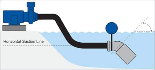
At the same time the available hot water will not be able to flow into the reserve tank. So, a floating foot valve is required to keep the outlet pipe sink in hot water.
Illustration of a typical floating foot valve is shown in Fig. 7. The floating ball will keep the outlet pipe submerged to ensure uninterrupted water flow.
After wiring the whole circuit, connect the power supplies (Fig. 3) to the main circuit (Fig. 2) via CON1 and CON2 for 5V and 12V, respectively. Turn on the power supplies.
The LDR1 will detect the intensity of light continuously. At day time, the signal at digital input pin 13 of the Arduino is low. The low signal at pin 13 will keep the relay (RL1) de-energised. So, the solenoid valve (SV) connected to NC contact of the relay will get energised, allowing cold water to flow into the solar water heater tank. The hot water is further stored in the reserve tank.
At night, the circuit will give a high signal to pin 13 of Arduino, which will energise the relay (RL1). This will disconnect the solenoid valve (SV) from the 12V power supply and stop the flow of cold water into the solar water heater tank.
Tej Vijaykumar Patel is B.E. in mechatronics and currently working as an engineer at SKAPS Industries India Pvt Ltd.