
The base setup for this system is located in a room with approximate dimensions of 9.29 square metre. The room is non-air conditioned and does not receive any direct sunlight. The proposed setup aims to evaluate the feasibility of utilising an electrode-based E201 BNC pH measurement sensor for assessing the pH of the water before and after the addition of liquid nutrients.
POC Video Tutorial In English:
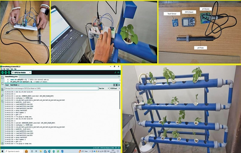
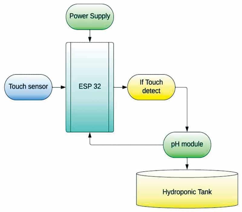
Fig. 1 illustrates the authors’ prototype showcasing various aspects of the setup and its installation. Monitoring the pH value is crucial for maintaining optimal conditions for plant growth. The ESP32 is employed in deep sleep mode, and with the assistance of a touch sensor, the pH of the hydroponic solution can be measured with a simple touch. This touch sensor acts as an interrupt, triggering an external input for the ESP32, thereby awakening it from deep sleep mode. Fig. 2 provides a block diagram representation of the entire setup.
pH reflects the hydrogen potential in a solution, providing a numerical value that determines its acidity or alkalinity. The pH scale ranges from 0 to 14. A pH value below 7 indicates acidity, while a value above 7 indicates alkalinity. pH serves as a vital chemical indicator for hydroponic setups, reflecting changes in water due to the addition, absorption, and balance of liquid fertilisers. Common indicators such as phenolphthalein, methyl red, and bromothymol blue are utilised to indicate pH ranges of approximately 8 to 10, 4.5 to 6, and 6 to 7.5, respectively.

Phenolphthalein transitions from colourless to pink, while methyl red transitions from red to yellow. This term, widely used in chemistry, biology, and agronomy, translates the concentration values of hydrogen ions, typically ranging between about 1 and 10–14 gram-equivalents per litre, into a scale from 0 to 14.
The pH of a solution can be calculated by taking the negative logarithm of the hydronium ion concentration, expressed as pH= -log[H3O+]. At 25°C, a solution with pH<7 is acidic, pH>7 is basic, and pH=7 is neutral.
There are two methods for measuring pH: colorimetric methods utilising indicator solutions or papers, and more accurate electrochemical methods using electrodes and a millivoltmeter (pH meter). We are employing the latter method with the aid of a microcontroller circuit for enhanced accuracy in readings.
Plants have varying pH requirements; however, a pH range of 5.5 to 6.5 is generally considered optimal for hydroponic gardening. Most plants thrive in slightly acidic conditions. The commonly used chemicals to adjust pH are phosphoric acid (to lower pH) and potassium hydroxide (to raise pH).
While both chemicals are relatively safe, they can cause burns and should never come in contact with the eyes.
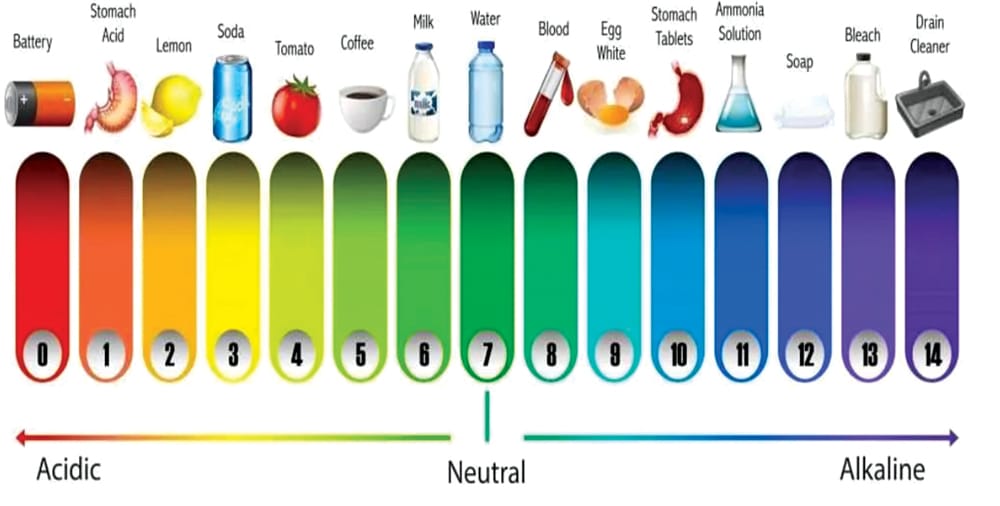
Specific nutrients necessitate certain pH levels for optimal plant uptake. Incorrect pH levels can lead to deficiencies in certain nutrients or toxicity. For instance, when the pH level drops below 5.0, plants may develop magnesium and calcium deficiencies, or copper and iron toxicity. Fig. 3 illustrates a typical pH scale and its correlation to everyday objects in our lives.
ESP32 power modes
Active mode. In this mode, all peripherals of the chip remain active, including Wi-Fi, Bluetooth, and radio based on program input.
Modem-sleep mode. The CPU is operational, and the clock is configurable. The Wi-Fi/Bluetooth baseband and radio are disabled.
Light-sleep mode. The CPU is paused, while the RTC memory, RTC peripherals, and the ULP co-processor are running. Wake-up events (MAC, SDIO host, RTC timer, or external interrupts) will awaken the chip.
Deep-sleep mode. Only the RTC memory and RTC peripherals are powered up. Wi-Fi and Bluetooth connection data are stored in the RTC memory. The ULP coprocessor remains functional.
Hibernation mode. The internal 8MHz oscillator and ULP co-processor are disabled. The RTC recovery memory is powered down. Only one RTC timer on the slow clock and specific RTC GPIOs are active. The RTC timer or RTC GPIOs can wake up the chip from hibernation mode.
The ESP32 deep sleep mode is utilised in the Arduino Cloud. In the current setup, the ESP32 microcontroller is initialised into deep sleep mode and awakened as needed. This can be achieved in three ways: timer wake up, touch wake up, and external wake up.
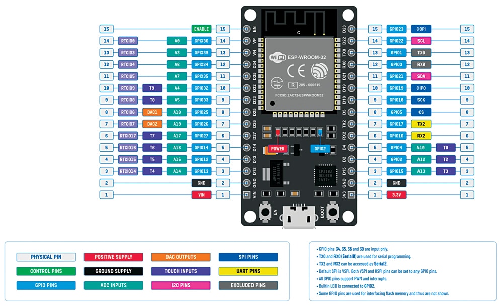
A comparison of the five different modes is provided in Table 1 from the ESP32 datasheet. The pinout is represented in Fig. 4, and Table 1 displays the various power modes and power consumption of the ESP32 chip.
| Table 1: Various power modes of operation and power consumption of ESP32 chip | ||||
| Power Mode | Description | Power Consumption | ||
| Active (RF working) | Wi-Fi Tx packet | — | ||
| Wi-Fi/BT Tx packet | ||||
| Wi-Fi/BT Rx and listening | ||||
| Modern sleep | The CPU is powered up | 240MHz | Dual-core chip(s) | 30mA~68mA |
| Single-core chip(s) | NA | |||
| 160MHz | Dual-core chip(s) | 27mA~44mA | ||
| Single-core chip(s) | 27mA~34mA | |||
| Normal speed: 80MHz | Dual-core chip(s) | 20mA~31mA | ||
| Single-core chip(s) | 20mA~25mA | |||
| Light sleep | — | 0.8mA | ||
| Deep sleep | The ULP coprocessor is powered up | 150µA | ||
| ULP sensor-monitored pattern | 100µA @ 1% duty | |||
| RTC timer + RTC memory | 10µA | |||
| Hibernation | RTC timer only | 5µA | ||
| Power off | CHIP_PU is set to low level, the chip is powered down | 1µA | ||
Timer wake up, touch wake up, and external wake up
Every setup has unique requirements. In this setup, the pH of the water circulated in the hydroponics setup is monitored using the E201 BNC. The ESP32 is maintained in deep sleep mode to conserve power consumption. The microcontroller wakes up using the external mode, which involves an attached touch sensor. Upon touch, the pH reading is taken, and the value is displayed on the serial monitor.
During deep sleep, some of the ESP32 pins can be utilised by the ULP coprocessor, namely, the RTC_GPIO pins and the touch pins. The ESP32 datasheet’s pinout identifies the RTC_GPIO pins, which are highlighted in a green rectangular box.
External wakeup
External wakeup is another method of waking up the ESP32 board from deep sleep mode, where a change in a GPIO pin’s state triggers the awakening. The wakeup source must be configured before setting the ESP32 board into deep sleep mode. Two types of external wakeups can be set up: ext0 and ext1. Ext0 involves configuring one GPIO pin as an external wakeup, while ext1 is used for multiple GPIO pins. It is important to note that only RTC GPIO pins can be used as a wakeup source for external wakeup.
To enable the ext0 wakeup source, use the following API:
esp_sleep_enable_ext0 wakeup()The RTC IO module is responsible for triggering the ext0 wakeup. As the RTC IO module is part of the RTC peripherals power domain, the RTC peripherals must be powered on during deep sleep mode when using ext0 as a wakeup source.
Software
The code is prepared in Arduino IDE. Here, the PIN is defined for the sensor, and then the pH value is extracted using a formula. In the setup function, the sensor data is processed with the sleep function to enable the processor to sleep and wake on time to process the sensor data. Fig. 5 shows a snippet of the source code.
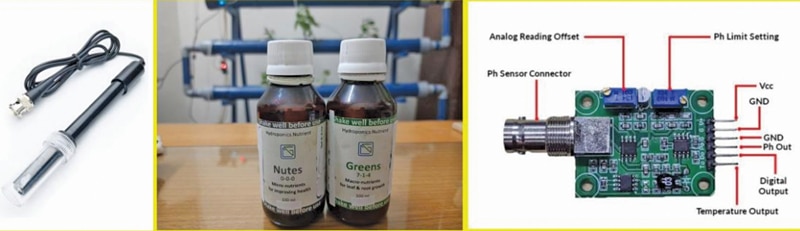
Fig. 6 represents additional information about the setup and the components used. The pinout of the sensing probe, along with the probe assembly, provides access to the pH readings, taking into account the adjustment of offsets due to analogue readings and pH limits. Table 2 displays the bill of materials, and Table 3 shows the pin connections for interfacing the sensor.
| Table 2: Bill of materials | ||
| Components | Amount | Description |
| ESP32 (MOD2) | 1 | For programming |
| pH sensor (MOD3) | 1 | To sense the pH value |
| Touch sensor (MOD1) | 1 | To initiate an external input for taking readings |
| Jumper wires (male to female) | 3 | To connect the sensor |
| Table 3 connections between mod1, mod2, and mod3 | |
| MOD3 (pH Sensor) | MOD2 (ESP32) |
| Voltage supply (5V) | Vcc (5V) |
| Output of sensor (A) | G35 |
| GND | GND |
| MOD1 (Touch Sensor) | MOD2 (ESP32) |
| Voltage supply (Vcc) | Vcc (5V) |
| Output of sensor (SIG) | G4 |
| GND | GND |

Circuit Diagram
The circuit is built around the touch sensor (MOD1), ESP32 (MOD2), pH sensor (MOD3), and a few jumpers. Fig. 7 illustrates the wiring of the proposed setup on the breadboard, and Fig. 8 shows the circuit diagram of the proposed system.
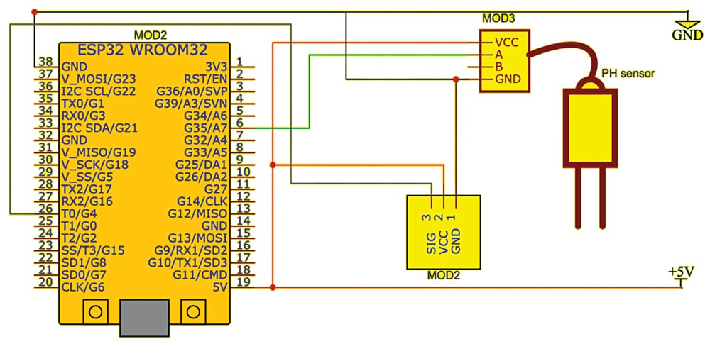
Before assembling the project, refer to Fig. 7 and 8. After proper assembly of the circuit based on the circuit diagram, upload the code to ESP32 and then test the device by powering it. You will receive the pH value in the serial monitor when you dip the sensor into the liquid to be measured.
Note. In conclusion, it is possible to measure the pH of a hydroponic solution using a sensor while conserving power by operating it in deep sleep mode.
Dr Geetali Saha is a faculty member at the Department of Electronics and Communication Engineering, GCET, Anand, Gujarat, and Dhruv Vachhani, a student coordinator from the 3rd Year CSE – IoT Department, is working on this sponsored project with Dr Saha