Monday, April 29, 2024

Reference Design For BLDC Fan Controller

A Brushless Direct Current (BLDC) fan controller design to implement thermal speed control in BLDC fans.

BLDC fan controller

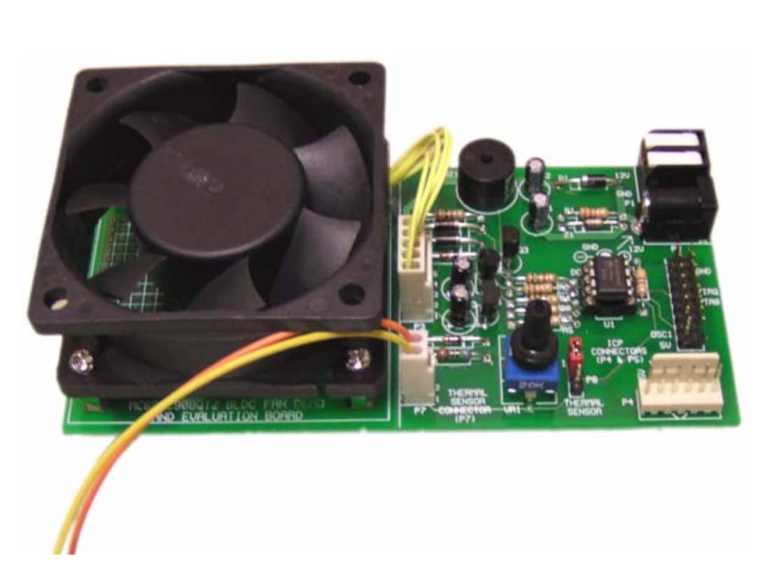
Over recent years, there has been a significant advancement in data processing equipment characterised by compact size, increased processing power, and higher speed. However, these performance improvements have increased demand for enhanced cooling capabilities, specifically in cooling fans. These requirements include variable speed control to minimise noise levels and conserve energy, efficient thermal management, protection against mechanical wear, and fault prevention. NXP has launched the reference design for Brushless Direct Current (BLDC) fan controllers, presenting a solution for implementing thermal speed control in BLDC fans. The design uses a simple speed control algorithm that effectively manages the fan’s speed in common scenarios prioritising factors like noise reduction, energy efficiency, thermal management, and fault protection.

The reference design is based on the 8-pin MC68HC908QT2 microcontroller unit (MCU) that adds a range of control functionalities to the design. These include auto-thermal speed adjustment, motor-lock protection, alarms for over-temperature and motor-lock conditions, in-circuit programming for firmware upgrades, and manual speed adjustment. The BLDC fan controller design consists of a BLDC fan, Hall effect sensor, MCU, regulator, transistors, thermal sensor, and buzzer. The fundamental functioning involves the MCU initiating the BLDC fan by driving the transistors. At the same time, the Hall effect sensor detects the fan’s position and alters the logic level accordingly. Using the signals from the Hall effect sensor, the MCU regulates the fan drive through a process called commutation. The fan’s speed is determined by the input received from an external thermal sensor. Based on this thermal sensor input, the MCU adjusts the off-time period accordingly.

The BLDC fan is powered by a regulated 12V, 1A power input. The piezoelectric buzzer is used in the motor-lock alarm circuit to detect temperature. A 350Hz, 15% duty cycle tone is used for the alarm circuit. To prevent over-current issues, the design includes a motor-lock protection circuit that halts the motor when the software detects a no Hall signal state lasting longer than 100ms. Additional capacitors and diodes are added to the design to filter higher voltage spikes. Temperature versus speed mapping is an integral part of the design, accounting for variations in application cooling requirements, thermal sensor characteristics, and motor characteristics. The firmware incorporates a thermal speed profile mapping with 256 steps, allowing easy customisation to meet specific user requirements.

This reference design has been tested by NXP. It comes with a Bill of Material (BOM), schematics, Printed circuit board (PCB) layout, etc. You can find additional data about the reference design on the company’s website. To read more about this reference design, click here.

Nidhi Agarwal
Nidhi Agarwal
Nidhi Agarwal is a journalist at EFY. She is an Electronics and Communication Engineer with over five years of academic experience. Her expertise lies in working with development boards and IoT cloud. She enjoys writing as it enables her to share her knowledge and insights related to electronics, with like-minded techies.

SHARE YOUR THOUGHTS & COMMENTS

Unique DIY Projects

Electronics News

Truly Innovative Tech

MOst Popular Videos

Electronics Components

Calculators