In this DIY article, I will be explaining how to interface X9C10X series of Digital Potentiometer with any microcontroller, for ease of explanation I will be using any of the board from Arduino eco system, but No libraries will be used. So, Let’s make a driver from scratch.
|
What is digital Potentiometer? A digital potentiometer is a digitally-controlled electronic component that mimics the analog functions of a potentiometer.  |
Before starting, let’s see the difference between a variable resistor/ mechanical potentiometer and digital potentiometer.
The Difference!
|
Variable Resistor / Potentiometer |
Digital Potentiometer |
|
Manual Control |
Controlled Through Microcontroller, can be automated |
Let’s get started,
You may download its datasheet from the following link for the reference:
X9C102, X9C103, X9C104, X9C503 Datasheet
This tutorial will work for the following series
X9C102(1 k Ω), X9C103(10k Ω), X9C104(100 k Ω), X9C503(50 k Ω)
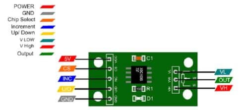
I will be using X9C103S 10 k Ω digital potentiometer.
The X9C103S 10k digital potentiometer module is a variable resistor whose resistance value can be varied digitally from a microcontroller. It consists of a 3-pin output which can replace a mechanical potentiometer which has 3 pins. This module can set 99 different resistances, and it is controlled by the 3-wire interface.
X9C103 Key Specifications
- The wiper has 100 tap points, which means that you can adjust the resistance value between 0 and 10 kilo ohms with 100 steps, therefore the resolution of each tap point will be 100 ohms.
- It also provides a function for storing a resistance value, which can be returned once power is turned off and on.
The potentiometer has 100 steps, so if it is connected across 5V, the step resolution of the wiper output will be approximately 5V/100 steps = 50mV.
It is not a true communication interface, and it is not possible to read the current setting back out of the device. This may seem like a major limitation, but it mimics how a typical potentiometer is used.
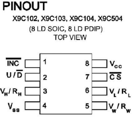
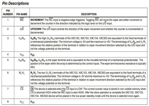
As we have pinout, let’s look at Pin Description attached below (screenshot taken from the datasheet)
Applications
The device can be used as a three-terminal potentiometer or as a two-terminal variable resistor in a wide variety of applications ranging from control to signal processing to parameter adjustment
For Writing Software driver following table from datasheet gives a clear picture.
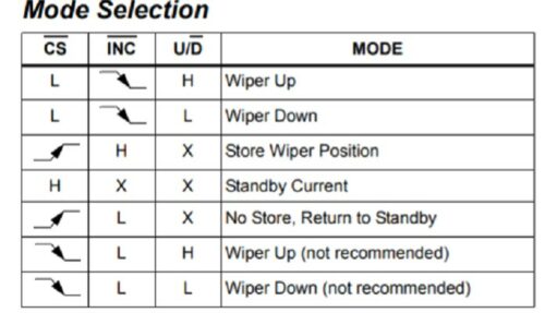
We need three GPIO Pins that needs to be connected to
- CS = Chip Select
- INC = Increment. Pulsing this pin low causes the wiper to move on the negative (falling) edge of the pulse.
- U/D = Up / Down. Determines the direction of travel of the wiper when the module is incremented. Logic HIGH moves the wiper UP, and logic LOW moves the wiper down.
Other Connection Details
- VCC = Vcc power (4.5 to 5.5V)
- GND = Ground
- VL = Voltage Low is the voltage for the lower end of the potentiometer. This is normally ground or the lower of two voltages.
- VW – Voltage Wiper is the voltage output of the adjustable wiper contact
- VH – Voltage High is the voltage at the upper end of the potentiometer. This is normally the higher voltage.
By This information, the driver firmware can be written easily.
The test code was checked using an Arduino uno; the connection was made as follows.
U/D to pin 4, INC to pin 6 and CS to pin 5, but these can be reassigned to any 3 digital pins.
We are connecting the pot across 5V and ground, and the wiper output is being input to A0
The test code x9c10x_test_code.ino is attached.