


The proposed International Space Station tracker, powered by the NodeMCU board, uses LEDs and a buzzer to indicate real-time ISS position.
The ISS tracker interfaces with the NASA API to access the ISS’s current location data. Storing the user’s longitude and latitude in the code, the device calculates the effective distance between the ISS and the user’s location.
POC Video Tutorial In English
POC Video Tutorial In Hindi
The system effectively indicates the ISS’s distance by utilizing LEDs and a buzzer. A formula checks if the ISS is overhead. The green LED lights up when the ISS is directly overhead, and red LEDs light up progressively as the ISS nears the user’s location.

Communication with astronauts or others in the vicinity is possible when the ISS passes over, assuming they are on the radio at that time. This communication, facilitated by the ISS’s radio repeater, requires an antenna.
The components needed to build the International Space Station Tracker are listed in the bill of materials table.

| Required Components | |
| Components | Quantity |
| NodeMCU (MOD1) | 1 |
| Red LEDs (LED1-LED7) | 7 |
| Green LED (LED8) | 1 |
| Resistor 220Ω (R1-R8) | 8 |
| Buzzer | 1 |
International Space Station Tracker – Circuit Diagram
The circuit diagram of the ISS tracker is shown in Fig. 2. The tracker is built around NodeMCU (MOD1), a green LED (LED1), seven red LEDs (LED2 through LED8), and eight 220-ohm resistors (R1 through R8).
International Space Station Tracker – Code
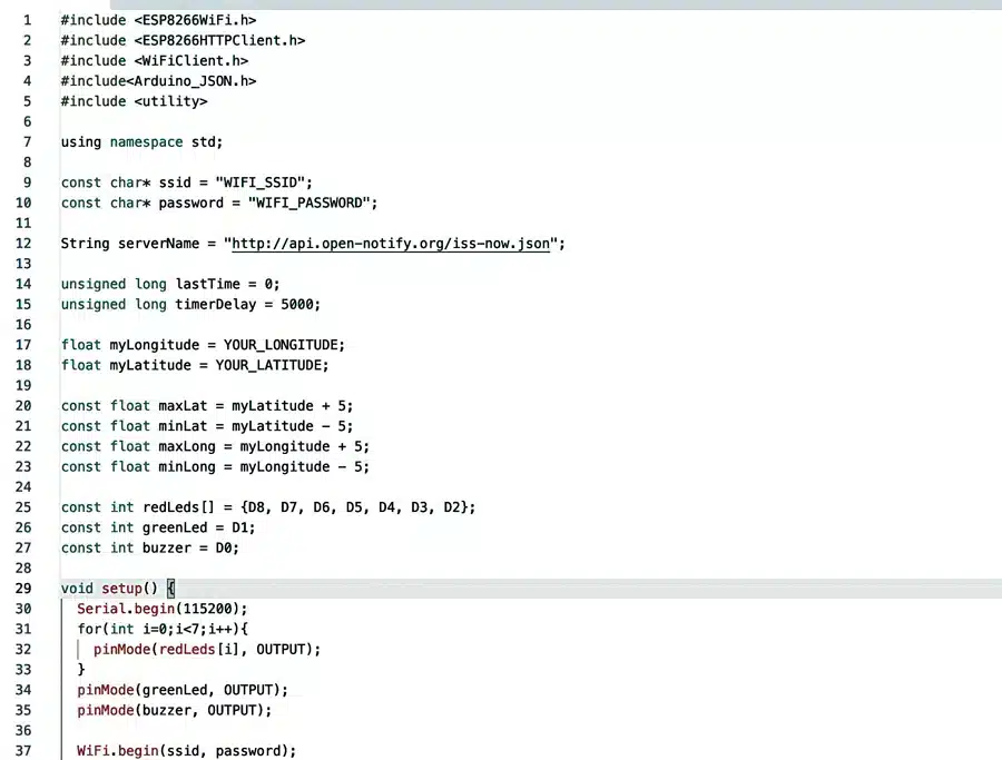
The code is prepared using Arduino IDE. In the first part of the code, the library for Wi-Fi configuration is added, and then the Wi-Fi credentials are set in the code, such as the SSID and password of the Wi-Fi network.
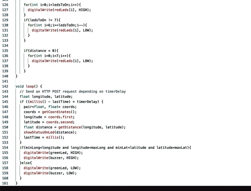
The server URL is set for obtaining the location of the ISS. In Fig. 3, the code snippet shows the Wi-Fi credentials, while Fig. 4 demonstrates the loop function acquiring the ISS distance.
Next, the loop function is set up to extract the distance of the ISS tracker and the LEDs (LED2 through LED8) glow according to the distance from the device location.
When the ISS comes closest to the device, the green LED1 starts glowing. Also, the buzzer sounds when the ISS comes just above the tracker.
Construction and Testing
First, select the correct port and board in the Arduino IDE and upload the code into NodeMCU.
Next, assemble the LEDs and resistors along with NodeMCU as per the circuit diagram shown in Fig. 2.
On powering the device, the LEDs will glow according to the ISS distance from the device.
The ISS tracker, built using the NodeMCU platform, serves as an engaging and educational tool for monitoring the International Space Station’s orbital patterns in real-time.
This device offers an exciting opportunity for enthusiasts to communicate with astronauts using the ISS’s radio repeater during its passes overhead.
Implementing this tracker keeps users informed about the ISS’s visibility, fostering a deeper appreciation for space exploration.
Pushpendra Chandravanshi, the author, is a passionate web developer and robotics enthusiast

Hi, I tried to compile this code in Arduino IDE, I am getting following error message:
‘YOUR_LONGITUDE’ was not declared in this scope
Can you please help and guide further….
got it…