


The DC/DC buck-boost converter adjusts input voltage to a stable output for industrial electronics, with a safety feature for low input voltage.
DC/DC buck-boost converters are crucial components in electronic systems for various reasons. They provide a stable output voltage from a variable input voltage source, essential for adequately operating sensitive electronic components. These converters are highly efficient in converting voltage levels, resulting in minimal energy loss and reduced heat generation compared to linear regulators. Their ability to increase (boost) or decrease (buck) the input voltage makes them versatile for various applications. In battery-powered devices, where battery voltage can fluctuate over its discharge cycle, buck-boost converters ensure consistent voltage supply, extending battery life and improving performance. Some buck-boost converters offer galvanic isolation between input and output, enhancing safety and reducing noise in sensitive applications.
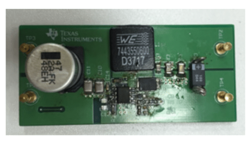
The PMP15012 reference design from Texas Instruments (TI) is a DC/DC buck-boost converter that takes an input voltage ranging from 18V to 36V and delivers a negative 15V/200mA output to the load. To address the challenge of shutting down a buck-boost converter, this design incorporates an external under-voltage lockout (UVLO) circuit to reduce the UVLO hysteresis. This LMR16020 buck-boost reference design is suitable for powering DACs, ADCs, and operational amplifiers (OAs) in industrial applications.

This device has a wide input voltage range from 18V to 36V and a negative 15V output. It includes an external under-voltage lockout (UVLO) circuit to reduce the buck-boost UVLO hysteresis. The converter employs peak current mode control and offers overcurrent protection (OCP) to prevent transformer saturation. Additionally, it comes with internal compensation for ease of use.
An under-voltage lockout (UVLO) circuit is a safety feature used in electronic devices and power converters. Its primary function is to prevent the device from operating when the input voltage falls below a specified threshold level. This is important because operating the device at a voltage lower than its minimum operating voltage can lead to unstable performance, reduced efficiency, and even potential damage to the device or its components.
The UVLO circuit continuously monitors the input voltage and turns off the device’s operation if the voltage drops below the set threshold. Once the input voltage rises above the threshold, the UVLO circuit allows the device to resume normal operation. This feature ensures that the device operates only under safe and optimal conditions, protecting the device and the system it is a part of.
Some of the design parameters of PMP15012 include:
- Input voltage: 18V to 36V
- Output voltage: -15V
- Output current: 0.2A
- Output Power: 3W
- Input type: DC
TI has tested this reference design. It comes with a bill of materials (BOM), schematics, etc. You can find additional data about the reference design on the company’s website. To read more about this reference design, click here.
