


 Health is characterized as a full state of physical, mental, and social well-being and not merely a lack of illness. Health is a fundamental element of people’s need for a better life. Unfortunately, the global health problem has created a dilemma because of certain factors, such as poor health services, the presence of large gaps between rural and urban areas, Physicians, and nurses’ unavailability during the hardest time.
The increased usage of Mobile devices and Smart devices like (Fitbit, Mi-Fit, Realme-Fit and etc.) and using IoT or GSM or Wi-Fi Module or Bluetooth Module for Monitoring the Health Parameters has made a great impact in the field of Health Care. Health Experts are taking more advantage of these technologies in their Clinical Dialysis of the Patients. There are more and more advantages available to using the IoT in the field of Health Care.
According to the constitutions of the World Health Organization (WHO), the highest attainable standard of health is a fundamental right for an individual. As we are truly inspired by this, we attempt to propose an innovative system that puts forward a smart patient health tracking system that uses sensors to track patient vital parameters and uses the internet to update the doctors so that they can help in case of any issues at the earliest preventing death rates.
This is the era of technology and automation. If automation is brought to a healthcare center, then it will be far more effective. Automation can be introduced in hospitals by the application of line following robots. A line following robot can act as a temporary nurse which can assist hospital staff in case of any emergency. Also, this kind of robot will work as a delivery robot in an operation room where doctors will need any extra accessories at any emergency instance. Robots have several useful applications in our daily.
Health Monitoring kit with IoT:
Patient Health Monitoring using IoT is a technology that enables to monitoring of patients without any physical contact with the patients. which may increase the access to care and decrease healthcare delivery costs. This can significantly improve an individual’s quality of life. It allows the patients to maintain the proper health condition reduces the risk and minimize personal costs. In addition, to this that patients and their family members feel comfort knowing that they are being monitored and will be supported if any problem arises. Medical personnel could be present in the place in order for guiding the People.
Medico Box:
Medico Box is a technology that uses IoT in order to enable the patients getting the Real Time Updating about the medicine to taken from Doctor or Physician. A Promising trend in healthcare is to move routine medical checks and other health care services from hospital. The use of IoT in Medicine Box has made with the help of Mobile Application. If the Correct Medicines based on the Update received from Doctor or Physicians are taken at the right time, there are less chances that the condition of the patient getting worse.
In this project, the intelligent medicine box will help a patient to take his/her medication when it is time to take and it depends on the health condition of the Patient. For example, if a patient has high temperature then it will open the Box1 which contains Medicine related to High Human Body in addition to this it will get the approval from the doctor before proceeding.
The body temperature, SpO2, pulse values and medicines taken data will be stored in a server which can be accessed by both patient and doctor so that when it is time the doctor can review the medicine and can change if needed. Also, it will be helpful for doctors to keep updated about the patient’s physical health condition.
IoT is rapidly revolutionizing the healthcare industry. In this project, we have designed the IoT-Based Patient Health Monitoring System using ESP8266 & Arduino. The IoT platform used in this project is Blynk. Blynk is a new platform that allows you to quickly build interfaces for controlling and monitoring your hardware projects from your iOS and Android device. IoT device could read the SpO2, and pulse rate and measure the surrounding temperature. It continuously monitors the SpO2, pulse rate and surrounding temperature and updates them to an IoT platform.
The Arduino Sketch running over the device implements the various functionalities of the project like reading sensor data, converting them into strings, passing them to the IoT platform, and displaying measured SpO2, Pulse rate and temperature on OLED Display and Blynk platform.
Block Diagram:

In this block diagram, the Temperature sensor, SpO2, and Pulse sensor are used to collect temperature and pulse readings. Communication can be done by the controller for sending the data to the IoT Platform. Data processing is to do at the server end. Thus the Temperature and Pulse Readings will be shown in the IoT Platform. A color sensor-based line follower robot is used to distribute the medicines and to hold the health monitoring kit with a medicine box.
Working System:
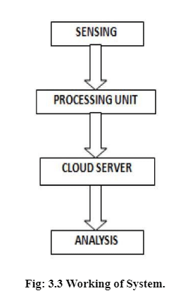
In this system the parameters are collected from the sensor are analyzed if any abnormal readings are found in Pulse or Temperature this system will inform the Doctor and will activate the Medical Box depending upon its need.
Components Used:
Arduino Uno:
Arduino’s processor essentially makes use of the Harvard structure in which this system code and application statistics have separate reminiscence. The code is saved inside the flash application reminiscence, while the statistics is saved within the side of the statistics reminiscence. The Atmega328 has 32 KB of flash reminiscence for storing code, 2 KB of SRAM, and 1 KB of EEPROM and operates with a clock pace of 16MHz.
The Arduino software program is well-matched with all styles of running structures like Windows, Linux, Macintosh, etc.
Battery 6V:
In electricity, a battery is a tool consisting of 1 or greater electrochemical cells that convert saved chemical electricity into electric electricity. A not unusual place electricity supply for lots family and business applications. There are sorts of batteries: number one batteries and secondary batteries.
A 6V battery is a lead-acid kind cell. It is likewise referred to as a lantern battery. It commonly makes use of 4 large. 6V batteries are utilized in canine schooling devices, clinical instruments, movie and virtual cameras, and plenty of different devices. A battery is a tool that converts chemical power immediately to electric power. It includes some of the voltaic cells; every voltaic molecular includes half-cells linked in collection through a conductive electrolyte containing anions and cations. One half-molecular consists of an electrolyte and the electrode to which anions migrate, and the opposite half-molecular consists of an electrolyte and the electrode to which cations migrate. Some battery cautions are connecting the charger, initial, bulk charge mode, absorption charge mode, and float charge. Battery types are lead-acid batteries, disposable batteries, and solar-powered batteries.
NODE MCU:
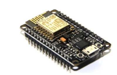
Node MCU is an open supply IoT platform. It makes use of many open supply projects, which includes Launceston, and spiffs. It consists of firmware that runs at the ESP8266 Wi-Fi, and hardware that’s primarily based totally on the ESP-12E module.ESP-12E is designed and evolved via way of means of Shenzhen Doctors of Intelligence & Technology (SZDOIT) primarily based totally on the Ultra-low energy intake UART-Wi Fi ESP8266, that’s mainly for cellular gadgets and alertness of IoT. Now, ESP-12E is broadly carried out to the internet, verbal exchange in the neighborhood area, clever home, business control, handed-gadgets, etc.ESP-12E Devitt has used the layout of the onboard antenna and encapsulated via way of means of 2. fifty-four direct insertion. It may be very handy to debug and deplumation the device. IN ESP12E Devitt, Hardware API operation is encapsulated via way of means of Lau language, which can keep away from the hardware trouble for software program engineers, after which can velocity the expansion of products. This is simply the ESP-12 chip. If you’re seeking out the breakout board with onboard regulator and preferred header compatibility.
Servo Motor:
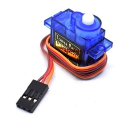
A servo motor is an electrical tool that can push or rotate an item with terrific precision. If you need to rotate the item at a few precise angles or distances, you then definitely use a servo motor. It is simply made of an easy motor which runs via servo mechanism.
Basically, servo cars are labeled into AC and DC servo cars relying upon the character of delivery used for its operation. Brushed everlasting magnet DC servo cars are used for easy programs attributable to their cost, performance, and simplicity. A servo includes a Motor (DC or AC), a potentiometer, tools meeting, and a controlling circuit. First of all we use tools meeting to lessen RPM and to boom torque of motor such that there may be no electric sign generated on the output port of the potentiometer. Servomotor features are linear dating among the rate and electric powered manage signal. , Steady country stability, Wide variety of pace management. The advantages of a servomotor are higher output than a 50Hz motor of the same size.
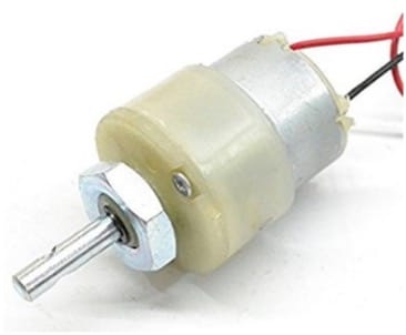
DC Motor:
L293D:
The L293D is designed to offer bidirectional force currents of as much as 600mA at voltages from four. five V to 36 V. gadgets is designed to force inductive masses inclusive of relays, solenoids, dc, and bipolar stepping motors, in addition to different high-current/high-voltage masses in positive-deliver applications. All inputs are TTL compatible. Each output is a whole totem-pole force circuit, with a Darlington transistor sink and a pseudo-Darlington source. Drivers are enabled in pairs, with drivers 1 and a couple of enabled through 1,2EN and drivers three and four enabled through three,4EN.
- OLED Display
- TCS230 Color Sensor
MAC3010:
The MAX30100 operates from 1.8V and 3.3V power supplies and can be powered down through software with negligible standby current, permitting the power supply to remain connected at all times
IoT Platforms
Internet of Things (IoT):
The internet of things, or IoT, is a tool of interrelated computing devices, mechanical and digital machines, objects, animals, or people which may be furnished with particular identifiers (UIDs) and the potential to interchange data over a network without requiring human-to-human or human-to-laptop interplay. An element within the internet of things can be a person with a coronary heart display screen implant, a farm animal with a biochip transponder, a car that has included sensors to alert the reason pressure whilst tire pressure is low or each different natural or man-made object that can be assigned an Internet Protocol (IP) address and is able to transfer data over a network. Increasingly, businesses in some industries are using IoT to carry out greater efficiency, better understand customers to deliver stepped-forward client service, decorate decision-making and growth the charge of the enterprise. How does IoT artwork? An IoT environment consists of web-enabled smart devices that use embedded systems, which include processors, sensors and communique hardware, to accumulate, deliver and act on data they accumulate from their environments. IoT devices percent the sensor data they accumulate with the resource of the usage of connecting to an IoT gateway or exceptional facet device in which data is each sent to the cloud to be analyzed or analyzed locally.
Sometimes, the ones devices talk with exceptional related devices and act on the information they get from one another. The devices do most of the artwork without human intervention, regardless of the reality that people will interplay with the devices — for instance, to set them up, deliver instructions or get proper access to the data. The sizeable set of packages for IoT gadgets is divided into numerous packages. These are the subsequent packages particularly customer application, clever domestic, clinical and tech care, transportation, constructing and domestic automation, commercial application, manufacturing, agriculture, infrastructure application, electricity control and environmental monitoring. While the idea of IoT has been in lifestyles for a prolonged time, a hard and fast of recent advances in a number of an incredible era has made it practical. They are Access to low-cost, low-energy sensor era, Connectivity, Cloud computing platforms, Machine learning and analytics, and Conversational artificial intelligence (AI). Industrial IoT refers to the application of IoT era in enterprise settings, specially with understanding to instrumentation and manipulation of sensors and devices that interact with cloud technologies. Recently, industries have used gadget-to-gadget communication (M2M) to gain wireless automation and manipulation.
BLYNK App:
Blynk is a brand new platform that lets in you to fast construct interfaces for controlling and tracking your hardware initiatives out of your iOS and Android device. The primary recognition of the Blynk platform is to make it super smooth to increase the cell telecellsmartphone application. As you may see on this course, growing a cell app that may speak in your Arduino is as smooth as dragging a widget and configuring a pin. With Blynk, you could manage an LED or a motor out of your cell telecellsmartphone with actually 0 programs. This is truly the primary test that I will show on this course. But don’t permit this simple to make you believe you studied that Blynk is simplest beneficial for trivial applications. Blynk is a strong and scalable device this is utilized by hobbyists and the enterprise alike.,. You also can use it to manipulate clever fixtures that may study out of your routines. Blynk is loose to apply for non-public use and prototyping. Their commercial enterprise version generates earnings with the aid of using promoting subscriptions to corporations that need to put up Blynk-powered apps for their hardware merchandise or services.
The BLYNK Smartphone App:
The Blynk app is absolutely an app editor. It permits you to create one or extra projects. Each mission can comprise graphical widgets, like digital LEDs, buttons, fee presentations or even a textual content terminal, and might have interaction with one or extra devices. With the assistance of the Blynk library, it’s far viable to govern Arduino or ESP32 pins immediately out of your phone, while not having to write down any code at all
The BLYNK Server:
The Blynk Cloud server is a fantastic desire for maximum projects, as it’s far from usually there, prepared to use. We will use the Cloud server withinside the first few experiments on this route that will help you get began out with minimum effort. However, as you may see, the Cloud Blynk server has imposed barriers. Some barriers are because of the topology of the server: relying to your geographical location. Blynk is the usage of the idea of “electricity” to put into effect a pricing gadget for its widgets. In the Cloud server you can begin a brand new mission with one thousand electricity gadgets. An LED widget might cost a little you two hundred gadgets, leaving 800 gadgets for the different widgets.
Code:
Blynk Code:
#define BLYNK_TEMPLATE_ID "TMPLPQjGEDeI"

#define BLYNK_DEVICE_NAME "SMART MEDICINE BOX"

#define BLYNK_AUTH_TOKEN

"NWtBlMvyHzcMaSdYxHu5PzLo7MSLAIWe"

#define BLYNK_PRINT Serial

#include <ESP8266WiFi.h>

#include <BlynkSimpleEsp8266.h>

#include <DHT.h>

#include <Wire.h>

#include "MAX30100_PulseOximeter.h"

#include <SPI.h>

#include <Wire.h>

#include <Adafruit_GFX.h>

#include <Adafruit_SSD1306.h>

#include <Servo.h> PulseOximeter pox;

uint32_t tsLastReport = 0;

#define REPORTING_PERIOD_MS     1000

float BPM, SpO2;

#define SCREEN_WIDTH 128 // OLED display width, in pixels

#define SCREEN_HEIGHT 64 // OLED display height, in pixels #define OLED_RESET     -1 // Reset pin # (or -1 if sharing Arduino reset pin)

#define SCREEN_ADDRESS 0x3C ///< See datasheet for Address; 0x3D for 128x64, 0x3C for 128x32

Adafruit_SSD1306 display(SCREEN_WIDTH, SCREEN_HEIGHT, &Wire,

OLED_RESET);

#define NUMFLAKES     10 // Number of snowflakes in the animation example

#define LOGO_HEIGHT   16 #define LOGO_WIDTH    16 char auth[] = BLYNK_AUTH_TOKEN; char ssid[] = "smart"; char pass[] = "smart@12345";

#define DHTPIN 2

#define DHTTYPE DHT11

DHT dht(DHTPIN, DHTTYPE);

BlynkTimer timer;

Servo servo1;

Servo servo2;

BLYNK_WRITE(V3)

{

  servo1.write(param.asInt());

}

BLYNK_WRITE(V4)

{

  servo2.write(param.asInt());

}

void sendSensor()

{   float h = dht.readHumidity();   float t = dht.readTemperature();   display.setTextSize(1);   display.setTextColor(1);   display.setCursor(0, 45);   display.println("Temp :");   display.setTextSize(1);   display.setTextColor(1);   display.setCursor(60, 45);   display.println(t);   display.display();   delay(1000);   if (isnan(h) || isnan(t)) {

    Serial.println("Failed to read from DHT sensor!");     return;

  }

  Blynk.virtualWrite(V2, t);


}void onBeatDetected()

{

  Serial.println("Beat!");

}

void setup()

{

  Serial.begin(115200);

  if (!display.begin(SSD1306_SWITCHCAPVCC, SCREEN_ADDRESS))

  {

    Serial.println(F("SSD1306 allocation failed"));     for (;;);

  }

  display.setTextSize(1.5);   display.setTextColor(1);   display.setCursor(0, 0);

  display.println("Initializing pulse oximeter..");

  display.display();

  Blynk.begin(auth, ssid, pass);   servo1.attach(14);   servo2.attach(13);

  Serial.print("Initializing pulse oximeter..");


  if (!pox.begin())

  {

    Serial.println("FAILED");     display.clearDisplay();     display.setTextSize(1.5);     display.setTextColor(1);     display.setCursor(0, 0);     display.println("FAILED");

    display.display();

    for (;;);   }   else   {

    display.clearDisplay();     display.setTextSize(1.5);     display.setTextColor(1);     display.setCursor(0, 0);     display.println("SUCCESS");     display.display();

    Serial.println("SUCCESS");

  }

  pox.setOnBeatDetectedCallback(onBeatDetected);    dht.begin();

  timer.setInterval(1000L, sendSensor);

} void loop() {    pox.update();

  if (millis() - tsLastReport > REPORTING_PERIOD_MS)

  {


    BPM = pox.getHeartRate();

    SpO2 = pox.getSpO2();

    Serial.print("BPM: ");

    Serial.println(BPM);

    Serial.print("SpO2: ");

    Serial.print(SpO2);

    Serial.println("%");

    Serial.println("*********************************");

    Serial.println();     display.clearDisplay();     display.setTextSize(1.5);     display.setTextColor(1);     display.setCursor(60, 0);     display.println(BPM);     display.setTextSize(1.5);     display.setTextColor(1);     display.setCursor(0, 0);     display.println("BPM :");     display.setTextSize(1.5);     display.setTextColor(1);     display.setCursor(0, 20);     display.println("Spo2 :");     display.setTextSize(1.5);     display.setTextColor(1);     display.setCursor(60, 20);     display.println(SpO2);     display.display();     tsLastReport = millis();     Blynk.virtualWrite(V0, BPM);

    Blynk.virtualWrite(V1, SpO2);

  }

  Blynk.run();   timer.run();

}
6.2) COLOUR SENSOR CODE:
#define M1 13

#define M2 12

#define M3 A0

#define M4 A1

#define M5 A2

#define M6 A3

#define M7 A4

#define M8 A5

#define PWM1 3

#define PWM2 9

#define PWM3 10

#define PWM4 11

#define S0 4

#define S1 5

#define S2 6

#define S3 7

#define sp 210

#define sensorOut 8 #define buz 2 int red = 0; int green = 0; int blue = 0; void setup() {   Serial.begin(9600);   pinMode(buz, OUTPUT);   pinMode(S0, OUTPUT);   pinMode(S1, OUTPUT);   pinMode(S2, OUTPUT);   pinMode(S3, OUTPUT);   pinMode(PWM1, OUTPUT); pinMode(PWM2, OUTPUT);   pinMode(PWM3, OUTPUT); pinMode(PWM4, OUTPUT);   pinMode(M1, OUTPUT); pinMode(M2, OUTPUT);   pinMode(M3, OUTPUT); pinMode(M4, OUTPUT);   pinMode(M5, OUTPUT); pinMode(M6, OUTPUT);   pinMode(M7, OUTPUT); pinMode(M8, OUTPUT);

  pinMode(sensorOut, INPUT);

  //scaling to 20 %   digitalWrite(S0, HIGH);   digitalWrite(S1, LOW);

}


void loop() {   color();

  if ( (( red >= 80) && ( red <= 100)) && (( green >= 195) && (  green <=

220)) && (( blue >= 150) && ( blue <= 165)) )

  {

    Serial.println("RED");     digitalWrite(M1, 1); digitalWrite(M2, 0); analogWrite(PWM1, sp) ;     digitalWrite(M3, 1); digitalWrite(M4, 0); analogWrite(PWM2, sp) ;     digitalWrite(M5, 1); digitalWrite(M6, 0); analogWrite(PWM3, sp) ;     digitalWrite(M7, 1); digitalWrite(M8, 0); analogWrite(PWM4, sp) ;

  }

  if ( (( red >= 215) && ( red <= 230)) && (( green >= 160) && (  green <=

180)) && (( blue >= 150) && ( blue <= 170)) )

  {

    Serial.println("GREEN");

    digitalWrite(M1, LOW); digitalWrite(M2, LOW);  analogWrite(PWM1, sp) ;//MOTOR 1

    digitalWrite(M3, HIGH); digitalWrite(M4, LOW); analogWrite(PWM2, sp) ; //MOTOR 2

    digitalWrite(M5, HIGH); digitalWrite(M6, LOW); analogWrite(PWM3, sp) ; //MOTOR 3

    digitalWrite(M7, LOW); digitalWrite(M8, LOW);  analogWrite(PWM4, sp) ; //MOTOR 4

  }

  if ( (( red >= 205) && ( red <= 220)) && (( green >= 115) && (  green <=

125)) && (( blue >= 75) && ( blue <= 90)) )

  {

    Serial.println("BLUE");

    digitalWrite(M1, HIGH); digitalWrite(M2, LOW); analogWrite(PWM1, sp) ; //MOTOR 1

    digitalWrite(M3, LOW); digitalWrite(M4, LOW);  analogWrite(PWM2, sp) ; //MOTOR 2

    digitalWrite(M5, LOW); digitalWrite(M6, LOW);  analogWrite(PWM3, sp) ; //MOTOR 3

    digitalWrite(M7, HIGH); digitalWrite(M8, LOW); analogWrite(PWM4, sp) ; //MOTOR 4

  }

  if ( (( red >= 65) && ( red <= 75)) && (( green >= 75) && (  green <= 85))

&& (( blue >= 100) && ( blue <= 110)) )

  {

    Serial.println("YELLOW");     digitalWrite(M1, LOW); digitalWrite(M2, LOW);     digitalWrite(M3, LOW); digitalWrite(M4, LOW);     digitalWrite(M5, LOW); digitalWrite(M6, LOW);     digitalWrite(M7, LOW); digitalWrite(M8, LOW);

    digitalWrite(buz, HIGH);delay(500);      digitalWrite(buz, LOW);delay(500);     digitalWrite(buz, LOW);      delay(10000);

    digitalWrite(M1, HIGH); digitalWrite(M2, LOW); analogWrite(PWM1,

180) ; //MOTOR 1

    digitalWrite(M3, HIGH); digitalWrite(M4, LOW); analogWrite(PWM2,

180) ; //MOTOR 2

    digitalWrite(M5, HIGH); digitalWrite(M6, LOW); analogWrite(PWM3, 180) ; //MOTOR 3

    digitalWrite(M7, HIGH); digitalWrite(M8, LOW); analogWrite(PWM4,

180) ; //MOTOR 4     delay(2500);

  }


  if ( (( red >= 275) && ( red <= 290)) && (( green >= 260) && (  green <=

270)) && (( blue >= 215) && ( blue <= 225)) )

  {

    Serial.println("BLACK");     digitalWrite(M1, LOW); digitalWrite(M2, LOW);     digitalWrite(M3, LOW); digitalWrite(M4, LOW);     digitalWrite(M5, LOW); digitalWrite(M6, LOW);     digitalWrite(M7, LOW); digitalWrite(M8, LOW);

  }


}

void color() {

  // Setting RED (R) filtered photodiodes to be read   digitalWrite(S2, LOW);   digitalWrite(S3, LOW);   // Reading the output frequency   red = pulseIn(sensorOut, LOW);

  delay(100);


  // Setting GREEN (G) filtered photodiodes to be read   digitalWrite(S2, HIGH);   digitalWrite(S3, HIGH);   // Reading the output frequency   green = pulseIn(sensorOut, LOW);

  delay(100);

  // Setting BLUE (B) filtered photodiodes to be read   digitalWrite(S2, LOW);   digitalWrite(S3, HIGH);   // Reading the output frequency   blue = pulseIn(sensorOut, LOW);

  delay(100);

}
Schematic Diagram and Output:
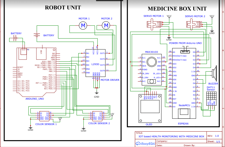
Robot Unit:
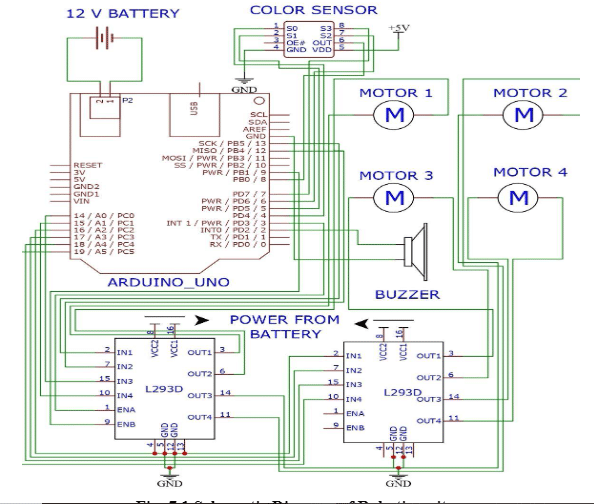
The above Figure 7.1 represents the robot unit schematic diagram. In which a 12V battery acts as supply to the circuit. The robotic unit contains a 12V battery, colour sensor, Arduino Uno, four motors and motor drivers. At first battery, supply is given to Arduino unit by input ports 1 and 2 and code is uploaded using USB port in the Arduino. Colour sensors input is connected with Arduino terminals.
The 4th pin in colour sensor is grounded and 5th pin is giving with an input of 5V supply. The output of the colour sensor is connected with the motor driver modules. There are three pins for input in motor drivers. The ports are 2, 7, 10, 15 respectively and the output pins are 3, 6, 14, 11. The pins 4, 5, 12, 13 acts as ground for the drivers and grounded. The pins 8 and 16 are supply pin which is connected with battery i.e. Power source. Then the output signals from the motor driver is sent to the 4 motors which is connected to the wheels of the robot car which rotates according to the colour input given to the colour sensor. Finally, buzzer produces sound when it senses yellow colour i.e. is programmed as patient for alert and moves straight in red colour, turns left in green colour and turn right when it senses blue colour.
Medical Box:

The above Figure 7.2 represents the medicine box unit’s schematic diagram. It contains two servo motors for opening and closing action of servo motors MAX 30100 sensor which is PULSE OXIMETER, OLED DISPLAY, NODE MCU, AND DHT11 TEMPERATURE SENSOR.
The whole circuit’s supply is given from the same battery. The NODE MCU is uploaded with code and which sent signals to the servo motor for the operations. MAX30100 sensor gathers the patients pulse rate and the DHT11 sensor gets patients body temperature measurements and sends it to NODE MCU where its processed and generates output signals. NODE MCU is connected with a OLED display it displays the pulse rate and temperature of the patient for reference.
The medicine box opens and closes according to the pulse and temperature parameters and the program for it initially uploaded in the NODE MCU module.
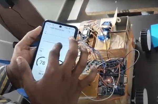
Output:
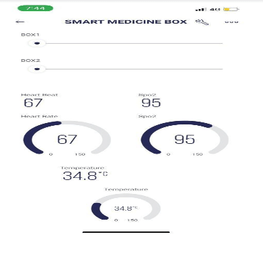
In the above Fig:7.3 the health measurements of Pulse, SpO2 and temperature are shown along with opening and closing of medicine box.

In the above Fig 7.4 the red color line denotes the robot to follow staright and blue color line denotes to follow right turn and green color line denotes to follow left turn and yellow denotes to wait with a buzzer.
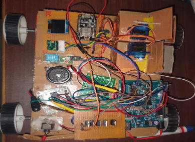
In the Fig:7.4 the kit containing health monitoring sensors like temperature, pulse and SpO2 in it along with the Medine Box.
