An IR remote switch is a wireless device that uses infrared (IR) signals from a remote control to operate electrical appliances. Commonly used in home automation, lighting control, and fan regulation, it enhances convenience and efficiency with seamless wireless switching.
The system consists of an IR receiver module, a signal processing circuit, and a relay to control the connected load. When an IR signal is detected, the receiver processes it and triggers a flip-flop circuit, activating the relay to switch the device on or off.
POC Video Tutorial
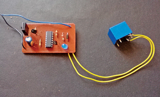
Any standard IR remote control, including those for televisions, CD players, or MP3 players, can be used. Fig. 1 shows the author’s prototype of IR Remote Switch.

| Parts List |
| Semiconductors: IC1 (IC1A-IC1C) – 4027 JK flip-flop T1, T2 – BC558 PNP transistor D1 – 1N4007 rectifier diode Resistors (all 1/4-watt, ±5% carbon): R1 – 100Ω R2, R4 – 1kΩ R3 – 180kΩ Capacitors: C1 – 100µF, 25V electrolytic C2 – 0.1µF ceramic disc C3 – 47µF, 25V electrolytic Miscellaneous: CON1-CON3 – 2-pin connector IR1 – TSOP1738 sensor module – 16-pin IC base – 5V battery or adaptor |
IR Remote Switch Circuit and Working
Fig. 2 illustrates the circuit diagram of the IR remote switch. The circuit is built around the TSOP1738 IR module (IR1), IC 4027 (IC1), two PNP BC558 transistors (T1, T2), a 5V SPDT relay, and a few passive components. The 16-pin IC 4027, a dual JK flip-flop, serves as the core of the circuit, with only one section used for this application.